
Resistance welding method suitable for multi-point circumferentially-arranged sheets

A circular arrangement and resistance welding technology, which is applied in the field of mechanical equipment and welding, can solve the problems of increased residual stress and welding deformation of workpieces, inability to realize workpiece welding, and high labor intensity of workers, so as to improve welding efficiency, improve welding quality and Welding efficiency and the effect of improving market competitiveness

Active Publication Date: 2015-04-22
SHIJIAZHUANG TIEDAO UNIV
View PDF5 Cites 0 Cited by
  • Summary
  • Abstract
  • Description
  • Claims
  • Application Information

AI Technical Summary

Problems solved by technology

[0005] The main disadvantage of the multi-point automatic spot welding device proposed in the above-mentioned patent documents is that the above-mentioned equipment applies welding pressure to a row of welding spots during welding, and other parts of the workpiece are in a suspended state, and the deformation is huge under the action of resistance welding pressure. , although the deformation in the welding process is reduced, but the deformation caused by the uneven force of the structure is increased; and the above-mentioned patented equipment cannot realize the welding of workpieces with circumferentially arranged welding spots
However, if the traditional resistance welding machine is used to perform resistance welding on the welding spots of the workpiece one by one, the welded parts will form a de facto constraint on the welding of the subsequent welding spots, and the resistance welding of the subsequent welding spots will also cause the residual stress and residual stress of the workpiece. The welding deformation increases, and the welding efficiency is very low, and the labor intensity of the workers is high

Method used


Image

  • Resistance welding method suitable for multi-point circumferentially-arranged sheets
  • Resistance welding method suitable for multi-point circumferentially-arranged sheets
  • Resistance welding method suitable for multi-point circumferentially-arranged sheets

Examples


Embodiment Construction

[0028] The present invention will be further described in detail below in conjunction with the accompanying drawings and specific embodiments.

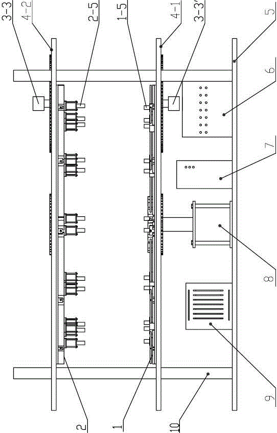
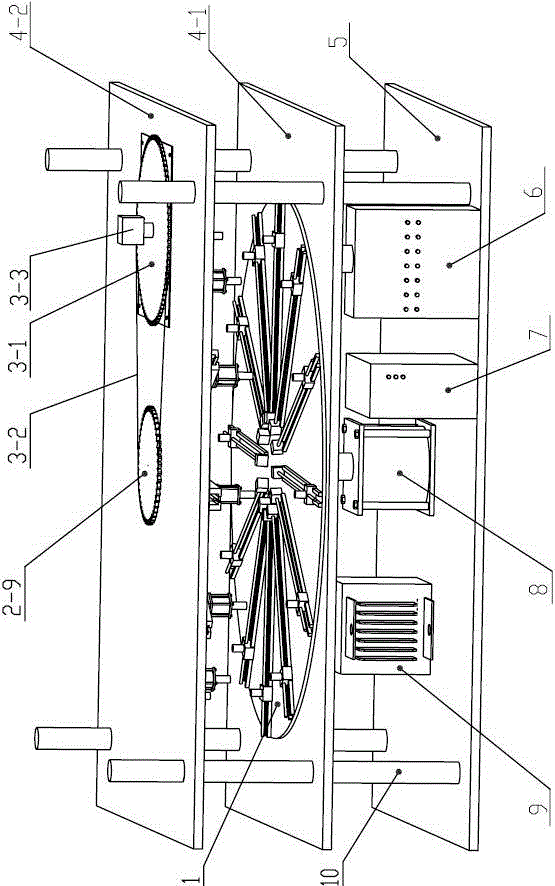
[0029] Such as figure 1 Shown is the structural representation of equipment of the present invention, figure 2 Shown is figure 1 A schematic diagram of the three-dimensional structure. The resistance welding equipment of the present invention includes a base 5 on which a PLC cylinder control cabinet 6, a stepping motor control cabinet 7, a lifting cylinder 8 and a transformer 9 are installed; the base 5 is arranged horizontally and fixed on the ground by bolts arranged at its four corners On, frame 10 is fixed on the base 5. The top of frame 10 is fixed with upper workbench 4-2, and last rotary tray 2 is installed on the bottom of upper workbench 4-2, and lower workbench 4-1 is installed between upper workbench 4-2 and base 5, and lower The rotating tray 1 is installed on the lower workbench 4-1, a pair of rotating trays 2 and 1 ...


PUM


Abstract

The invention discloses a resistance welding apparatus and method suitable for multi-point circumferentially-arranged sheets. The resistance welding apparatus comprises a base and a framework fixed on the base, wherein the base is provided with a PLC (programmable logic controller) cylinder control cabinet, a stepping motor control cabinet and a transformer; the framework is provided with a pair of rotating trays which are opposite to each other; each tray is provided with a radial guide rail; and a pair of upper and lower electrode tips is arranged on the guide rail and can radially move along the guide rail. The invention can realize the multi-point circumferential symmetry welding of workpieces, ensures that the workpieces are always in a stress balanced state, can effectively reduce or eliminate welding deformations, and simultaneously controls the quantity of pressed electrode tip pairs in the welding process to satisfy the variation of the quantity of welding points of the workpieces in different radial positions, thereby greatly improving the welding efficiency and reducing the labor intensity of workers. Thus, the invention is especially suitable for the welding of multi-point circumferentially-arranged sheet workpieces subjected to mass production; and the welding quality and welding efficiency can be improved, and the market competitiveness of the enterprise can be improved.

Description

technical field [0001] The invention belongs to the field of welding technology and mechanical equipment technology, and in particular relates to a resistance welding method for multi-point circumferentially arranged thin plates. Background technique [0002] Resistance welding is to compress the workpiece to be welded between two electrodes, and apply current, and use the resistance heating effect generated by the current flowing through the contact surface of the workpiece and the adjacent area to heat it to a molten or plastic state, so that it forms a metal bond. way. Resistance welding is a welding method with stable welding quality, high production efficiency, and easy mechanization and automation. It has developed rapidly since it came out at the end of the nineteenth century and is widely used in aviation, aerospace, chemical industry, automobiles, light industrial appliances, etc. industry. With the rapid development of the manufacturing industry in recent years, ...

Claims


Application Information

Patent Timeline
Patent Type & Authority Patents(China)
IPC IPC(8): B23K11/10B23K11/31B23K11/36B23K37/047
Inventor 齐海波任德亮李江飞侯哲哲丁占来
Owner SHIJIAZHUANG TIEDAO UNIV
Learn More