Realization method for mechanical arm calibrating and tracking system based on visual motion capture

A motion capture and tracking system technology, applied in manipulators, program-controlled manipulators, manufacturing tools, etc., can solve the problems of initial state deviation, inability to restore, and difficulty in relative motion restoration, and achieve good application prospects and accurate calibration.

Active Publication Date: 2013-01-02
ZHEJIANG UNIV
View PDF4 Cites 32 Cited by
  • Summary
  • Abstract
  • Description
  • Claims
  • Application Information

AI Technical Summary

Problems solved by technology

And it needs to be emphasized that the current vision-based motion capture is to restore the absolute pose of the target object (such as the current angle of each joint of the robot arm), and cannot measure the relative motion of each part of the target (such as the relative motion of each joint of the robot arm relative to the initial position). How many angles the state has moved) to restore, and because the initial state of the target will be biased due to errors or human influences, it is more difficult to restore relative motion

Method used


Image

  • Realization method for mechanical arm calibrating and tracking system based on visual motion capture
  • Realization method for mechanical arm calibrating and tracking system based on visual motion capture
  • Realization method for mechanical arm calibrating and tracking system based on visual motion capture

Examples


Embodiment Construction

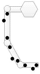
[0045] The implementation of the method and system for robot arm joint calibration and joint angle calculation using a visual motion capture system according to the present invention will be described in detail below with reference to the accompanying drawings. In this example, the system can calibrate the joints of the manipulator (give the initial position of the joints), obtain the rotation angle of each motor in the joints in real time, and reproduce the scene in the three-dimensional virtual space.

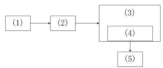
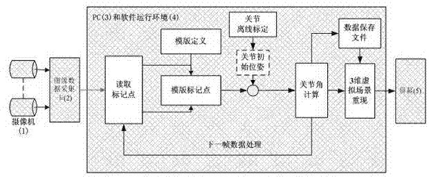
[0046] figure 1 The hardware structure diagram of the system is given. The whole system is composed of more than 8 cameras 1 , image data acquisition card 2 , main control computer 3 , visual software 4 , and external display screen 5 . The cameras are centered on the manipulator, with a radius of 3-5 meters and are evenly distributed in a ring shape. The height above the ground is 2-2.5 meters. The card transmits the collected data to the calibration program of the main con...


PUM


Abstract

The invention relates to a method for calibrating a mechanical arm joint and calculating a rotating angle based on visual motion capture and discloses a mechanical arm calibrating and tracking system based on the visual motion capture. The mechanical arm calibrating and tracking system comprises an optical driven motion capture system, computer master control equipment, visual software and an external display screen. The mechanical arm calibrating and tracking system comprises the following modules including a motion capture data acquiring and processing module, a mechanical arm joint calibration module, a joint angle calculation module and a three-dimensional virtual scene reproducing module based on OpenGL. The invention can be used as a practical and effective solution for calculating the mechanical arm joint and calculating the angle and has a favorable application prospect.

Description

technical field [0001] The invention relates to a method for calibrating and calculating rotation angles of mechanical arm joints based on visual motion capture. Background technique [0002] Manipulators are widely used in industrial production, military, aerospace, robotics and other fields, and the precision of the movement of the manipulator directly affects its performance. Feedback control of the manipulator needs to obtain the state of each joint, including the absolute angular position of the current joint and the relative angle of the motor relative to the initial state movement. Although traditional contact detection elements (such as potentiometers, Hall, etc.) can be used to obtain Precise values, but requires modifications to the robotic arm, which may affect its kinematic performance. Therefore, it is an ideal solution to use a non-contact visual capture system based on high precision and high speed to obtain the state of the robotic arm and joints. [0003] ...

Claims


Application Information

Patent Timeline
Patent Type & Authority Applications(China)
IPC IPC(8): B25J9/16B25J13/08
Inventor 刘杰华章逸丰熊蓉褚健
Owner ZHEJIANG UNIV
Why Eureka
Try Eureka