Hydraulic drive system with a plurality of hydraulic pumps and an energy recovery

A drive system, hydraulic pump technology, applied to fluid pressure actuating system components, fluid pressure actuating devices, servo motors, etc. Effect

Inactive Publication Date: 2013-01-02
ROBERT BOSCH GMBH
View PDF5 Cites 4 Cited by
  • Summary
  • Abstract
  • Description
  • Claims
  • Application Information

AI Technical Summary

Problems solved by technology

If the pressure drop is too high, it will cause cavitation on the fluid input of the working pump, which may damage it

Method used


Image

  • Hydraulic drive system with a plurality of hydraulic pumps and an energy recovery

Examples


Embodiment Construction

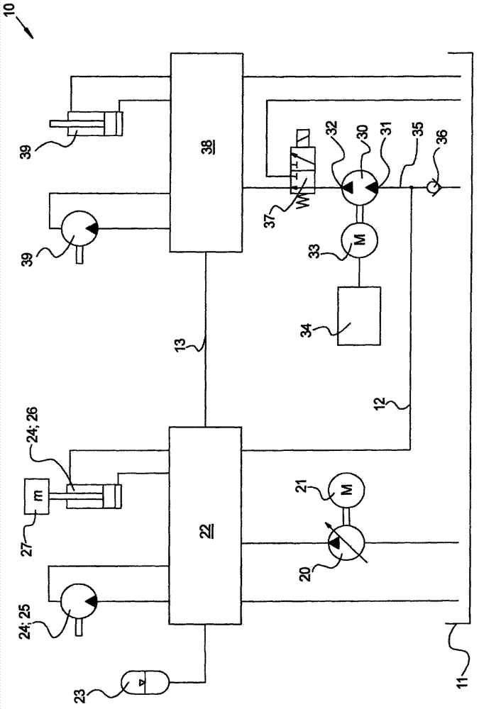
[0020] according to figure 1 The hydraulic drive system 10 includes an oil tank 11 filled with hydraulic fluid, especially hydraulic oil, under ambient pressure. The first hydraulic pump 20 draws hydraulic fluid from the tank 11 for supply to preferably a plurality of first consumers 24 . The first hydraulic pump 20 has an adjustable displacement so that only the fluid flow required by the first consumer 24 can be delivered to avoid energy losses. The first hydraulic pump 20 is preferably designed as a slant-axis or swash-plate machine and is driven by a diesel engine 21 .

[0021] The first consumer 24 is preferably a consumer that performs mechanical work. In particular, consumers are conceivable that carry out various working movements of the mobile work machine (not shown). For example, the hydraulic motor 25 is used for the undercarriage, for the movement of the superstructure which is rotatably movable relative to the chassis or for driving the winch. Hydraulic cylin...


PUM


Abstract

The invention relates to a hydraulic drive system (10) having a first and a second hydraulic pump (20, 30), wherein the first and the second hydraulic pump (20, 30) can promote hydraulic fluid to each of at least one associated first (24) and at least one associated second supply consumers (39) with hydraulic fluid, wherein said second hydraulic pump (30) having a fluid input (31) and a fluid output (32), wherein the fluid inlet (31) with a tank (11) is connected, so that the second hydraulic pump (30) of hydraulic fluid from the tank (11) suck in can,. According to the invention, the fluid inlet (31) of the second hydraulic pump (30) via a return line (12) is connected to at least one first consumer (24), that of the at least one first load (24) back-flowing hydraulic fluid at a pressure above ambient pressure in the second hydraulic pump flow (30).

Description

technical field [0001] The invention relates to a hydraulic drive system according to the preamble of claim 1 . Background technique [0002] Mobile work machines having first and second hydraulic pumps are already known. A first hydraulic pump (also referred to as a working pump) is used to supply generally a plurality of first consumers, such as travel drives with wheels or tracks, drives for rotatable superstructures, drives for movable booms with multiple joints drive unit or steering system. The movement of the individual consumers is controlled by means of the first control device, in particular by means of a valve group comprising a plurality of valve discs divided for the various consumers. The fluid flow of the first hydraulic pump is distributed to the individual consumers preferably according to the principle of load-dependent flow distribution (LUDV), wherein other control principles are also conceivable, such as load sensing or open center. Working pumps gene...

Claims


Application Information

Patent Timeline
Patent Type & Authority Applications(China)
IPC IPC(8): F15B11/17F15B1/02F15B11/024
CPCF15B2211/613F15B11/17F15B2211/20576F15B2211/71F15B2211/88F15B2211/20546F15B11/024F15B21/14F15B1/02
Inventor J・阿姆赖因
Owner ROBERT BOSCH GMBH
Why Eureka
Try Eureka