

Starter output shaft and processing technology thereof
A processing technology and output shaft technology, which is applied to engine components, metal processing equipment, shafts, etc., can solve the problems of unstable products, inconsistent press-fit interference, and larger output shaft aperture tolerances, and can solve the problems of planetary gear shafts. The effect of falling off, reducing product processing cost, and reducing forging deformation
- Summary
- Abstract
- Description
- Claims
- Application Information
AI Technical Summary
Problems solved by technology
Method used
Image

Examples
Embodiment Construction
[0023] The present invention will be described in further detail below in conjunction with the accompanying drawings.
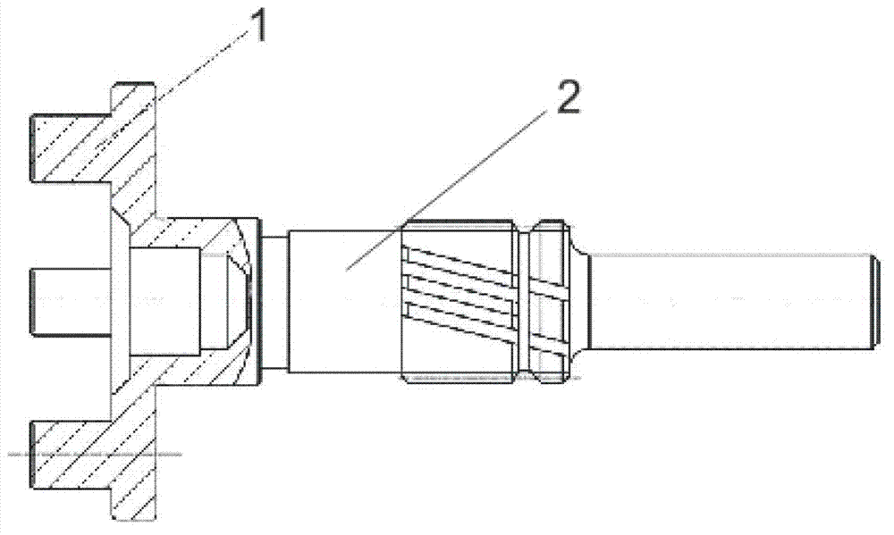
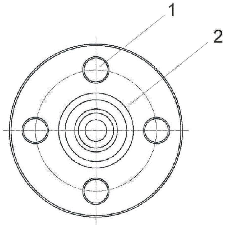
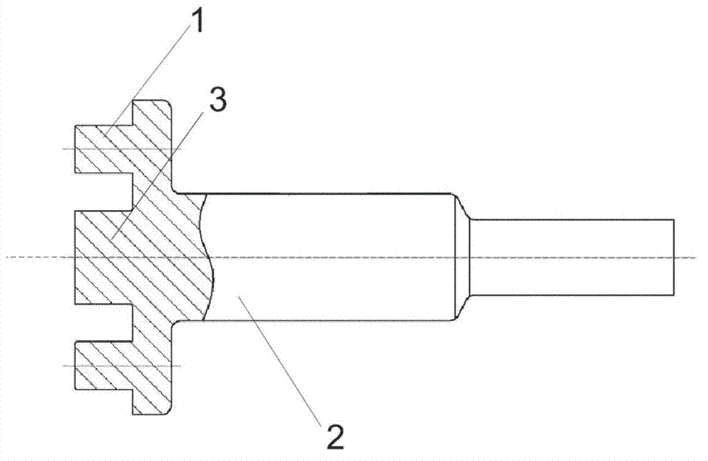
[0024] Such as Figure 1 to Figure 4 As shown in the figure, 1, planetary gear shaft; 2, output shaft; 3, shunt boss; 501, electromagnetic switch; 502, gear; 503, shift fork; One-way device; 505b, output shaft; 505c, ring gear; 505d, planetary gear; 505b 1 , output shaft; 505b 2 , Planetary gear shaft.
[0025] Reference herein to "one embodiment" or "an embodiment" refers to a particular feature, structure or characteristic that can be included in at least one implementation of the present invention. "In one embodiment" appearing in different places in this specification does not all refer to the same embodiment, nor is it a separate or selective embodiment that is mutually exclusive with other embodiments.
[0026] In the description of the present invention, the terms "upper", "lower", "left", "right", "front", "rear", etc. indicating orientation or po...
PUM
 Abstract
Description
Claims
Application Information