Power inductance element formed by molding and manufacturing method thereof

A technology of molding and power inductors, which is applied in the manufacture of electrical components, inductors/transformers/magnets, inductors with magnetic cores, etc., can solve the problem of affecting the degree of closeness, limiting automatic production, and the difficulty of producing magnetic heat shrinkable sleeves And other issues

Active Publication Date: 2013-01-02
SUNLORD (SHANGHAI) ELECTRONICS CO
View PDF7 Cites 27 Cited by
  • Summary
  • Abstract
  • Description
  • Claims
  • Application Information

AI Technical Summary

Problems solved by technology

Among them, the degree of shrinkage of the heat shrinkable sleeve will affect the degree of closeness, so the electrical characteristics of the molded product fluctuate greatly
In addition, the assembly of heat shrinkable sleeves also limits automated production
In addition, for smaller products, the production of magnetic heat shrink sleeves is also difficult to achieve, and the difficulty of assembly is also greatly increased

Method used


Image

  • Power inductance element formed by molding and manufacturing method thereof
  • Power inductance element formed by molding and manufacturing method thereof
  • Power inductance element formed by molding and manufacturing method thereof

Examples


Embodiment Construction

[0042] The present invention will be further described in detail below through embodiments in conjunction with the accompanying drawings.

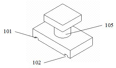
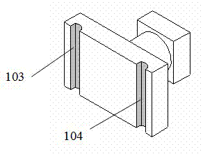
[0043] Such as Figure 1A1 , 1A2 As shown, the NiZn ferrite I-shaped magnetic core can be made by injection molding process, the magnetic permeability is preferably 3000~5000, and the saturation magnetic flux is 400~500mT. Preferably, there are two parallel electrode slots 101, 102 at the bottom of the magnetic core. The metallization layers 103 and 104 are preferably formed inside the electrode groove by a sputtering process.

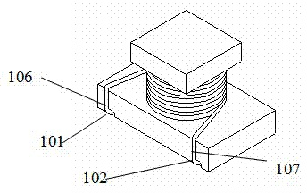
[0044] A winding machine can be used to wind the wire on the above-mentioned I-shaped magnetic core center column 105 . Such as Figure 1B As shown, preferably, the coil lead-out ends 106, 107 are received into the electrode slots 101, 102 after the coil winding product is completed.

[0045] Figure 1C It is a schematic diagram of the finished product formed after wrapping the winding with a magnetic plastic ...


PUM


Abstract

The invention discloses a power inductance element formed by molding. The power inductance element comprises a prefabricated magnetic core, a coil and a magnetic plastic package layer, wherein the coil is placed on the prefabricated magnetic core; the magnetic plastic package layer is formed by molding and is used for covering the magnetic core and the coil; and an electrode connected with the coil is exposed. The invention also discloses a method for manufacturing the power inductance element formed by molding. The method comprises the following steps of: a, prefabricating the magnetic core and placing the coil on the prefabricated core; and b, covering the magnetic plastic package layer on the magnetic core and the coil by virtue of molding and exposing the electrode connected with the coil. The power inductance product has the advantages of thinning, miniaturization and high reliability.

Description

technical field [0001] The invention relates to a molded power inductance element and a manufacturing method. Background technique [0002] With the development of IC technology, the overall requirements for power inductors are miniaturization, thinning, high frequency, low DCR, high current, low EMI (electromagnetic interference) and low manufacturing cost. Traditional process type power inductors, such as open magnetic circuit or open air gap magnetic sleeve inductors, are increasingly unable to meet the requirements of IC development. [0003] For ordinary open magnetic circuit power inductor products, although a higher frequency of use can be achieved, the size and quality of the device itself are relatively large, and there are serious EMI problems. [0004] For magnetic ring or magnetic barrel type closed magnetic circuit winding power inductor products, although the EMI problem can be better solved, and the rated current of the product can also be achieved to a great...

Claims


Application Information

Patent Timeline
Patent Type & Authority Applications(China)
IPC IPC(8): H01F17/04H01F27/24H01F27/30H01F41/00
Inventor 夏胜程侯勤田杨亚冰吴锦超何海根
Owner SUNLORD (SHANGHAI) ELECTRONICS CO
Why Eureka
Try Eureka