Antenna device of mobile terminal surrounding feed pin

A mobile terminal antenna and mobile terminal technology, applied in the direction of making the antenna work in different bands at the same time, the connection of the antenna, the antenna grounding switch structure, etc., can solve the problem of increasing the antenna clearance, not meeting the requirements of the mobile terminal, and not adopting the antenna structure The means of adjusting the length of the antenna, etc., to achieve the effect of increasing the height of the antenna

Inactive Publication Date: 2013-01-02
GUANGDONG BUBUGAO ELECTRONICS IND
View PDF6 Cites 3 Cited by
  • Summary
  • Abstract
  • Description
  • Claims
  • Application Information

AI Technical Summary

Problems solved by technology

[0008] The above-mentioned existing technologies have some shortcomings. Increasing the headroom of the antenna obviously does not meet the requirements of the mobile terminal for the antenna. To enhance the high and low frequency coupling of the G-type antenna may be to enhance the coupling of the high and low frequency branches. The gap between the two may be small enough to process Within the error range, mass production cannot be realized. In addition, in order to couple the second resonance of the long branch of the G-shaped antenna with the short branch, the end of the long branch generally needs to be folded back. s position
The scheme of series large inductance will introduce inductance loss, and will reduce the bandwidth of low frequency
The purpose of the above various antennas is to obtain broadband effects at multiple frequencies, thereby improving the utilization rate of bandwidth, but the structures of the above-mentioned devices are relatively complicated, and the antenna structure formed around the contact area of ​​the feeder foot as in the present invention and the antenna length adjustment are not adopted. s method

Method used


Image

  • Antenna device of mobile terminal surrounding feed pin
  • Antenna device of mobile terminal surrounding feed pin
  • Antenna device of mobile terminal surrounding feed pin

Examples


Embodiment Construction

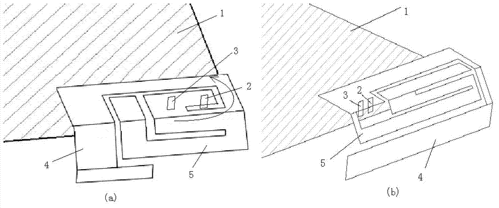
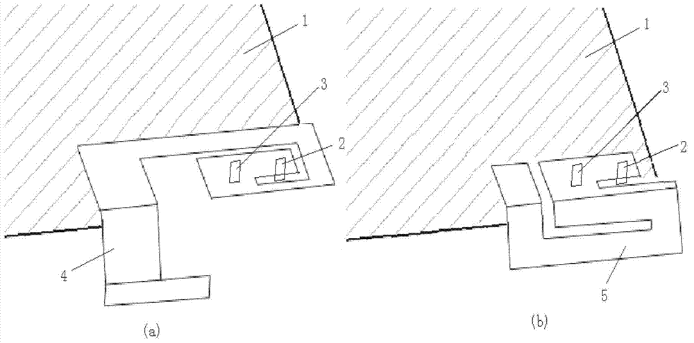
[0032] Below, combined with figure 1 And attached figure 2 , the specific embodiment of the present invention will be further described.

[0033] Such as figure 1 As shown, a preferred embodiment of the present invention is a mobile terminal antenna device that surrounds the feed pin, including the mobile terminal main board 1, the feed pin 2, the feed pin 3, and the antenna radiation around the feed pin or the contact area of ​​the feed pin The antenna radiation sheet includes a long branch 4 and a short branch 5 . As shown in Figure 1a, the long branch 4 of the antenna circles more than half a circle around the contact area between the feeder foot 2 and the feeder foot 3 in the direction of the arrow, so that when the primary resonance frequency of the long branch 4 is 1.57GHz, the second The resonant frequency is also higher than the 2.4GHz frequency band, and then the short branch 5 is used to further reduce the high frequency resonant frequency of the antenna, which j...


PUM


Abstract

The invention provides an antenna device of a mobile terminal surrounding a feed pin. The antenna device comprises a main board of the mobile terminal, an antenna feed pin and an antenna radiation film, and the antenna radiation film is provided with at least one long node surrounding the feed pin or a contact area of the feed pin. The antenna device provided by the invention has a higher compatibility in high and low frequency bands than a normal antenna, in particular in a situation that the normal antenna has a too high secondary resonance frequency due to a low-frequency node, without additionally increasing the antenna height, area and clearance or providing an additional large inductor connected in series. The antenna device of the mobile terminal surrounding the feed pin can be widely applied to a GSM (global system for mobile communications), a CDMA (code division multiple access) multi-frequency mobile terminal antenna and a WIFI (wireless fidelity), BT (Bluetooth) and GPS (global positioning system) three-in-one antenna.

Description

technical field [0001] The invention relates to a mobile terminal antenna device surrounding a feeder pin or a feeder pin contact area. Background technique [0002] Now, with the miniaturization and multi-frequency of mobile terminals, severe challenges are posed to the miniaturization of antennas and multiple operating frequency bands. For example, the three-in-one antenna of GPS, BT and WIFI needs to work in two frequency bands of 1.57GHz and 2.4GHz. If the common dual-frequency antenna technology is used, such as the "G" type antenna, which uses double-branch wiring to generate dual-frequency resonance, even if the coupling strength of the low-frequency branch and the high-frequency branch is increased, it is difficult to make the 1.57GHz branch The second resonance frequency falls near 2.4GHz, which will cause the 1.57GHz branch to interfere with the resonance of the 2.4GHz branch, resulting in a smaller bandwidth at 2.4GHz. [0003] In order to solve this technical p...

Claims


Application Information

Patent Timeline
Patent Type & Authority Applications(China)
IPC IPC(8): H01Q1/36H01Q1/50H01Q5/01H01Q5/10
Inventor 陈玉稳
Owner GUANGDONG BUBUGAO ELECTRONICS IND
Why Eureka
Try Eureka