Device and method for positioning and conveying of automatic sheet-fed die-cutting machine

A conveying device, single-sheet technology, applied in the orientation of objects, transportation and packaging, and object separation, etc., can solve the problems of limited paper conveying speed, influence of positioning accuracy, and decreased positioning stability, to ensure the accuracy of paper feeding, realize the Deterministic positioning and high-precision effects

Active Publication Date: 2013-01-09
SHANGHAI YOCO PRINTING MACHINERY
View PDF9 Cites 30 Cited by
  • Summary
  • Abstract
  • Description
  • Claims
  • Application Information

AI Technical Summary

Problems solved by technology

[0005] Both of the aforementioned two paper feeding methods are non-deterministic paper feeding positioning mechanisms, and there are some obvious disadvantages
[0006] figure 1 When the lower sucker-type paper feeding mechanism shown is feeding and positioning, the cardboard is conveyed forward by the counter-rolling of the paper receiving roller 14 and the belt power roller 15, so a certain relative pressure is required, so the corrugated cardboard is moved forward during the paper feeding process. The trace line is easily collapsed by the paper receiving roller 14, and the paper feeding speed of this mechanism is limited, and a relatively complicated structure is required to complete various actions
When the trailing edge of the cardboard leaves the receiving roller 14 and the belt power roller 15 and the cardboard has not reached the front gauge 19, the cardboard is clamped by the rubber pressure wheel 17 and the paper feeding belt 16, and the cardboard can be moved forward smoothly to a certain extent. However, if one of the paper feeding belts 16 is loose or the pressure of the rubber pressure roller 17 is uneven, it may cause the paper to be skewed
Moreover, when the front edge of the cardboard reaches the front gauge 19, due to the need for side regulation positioning, the cardboard cannot be pressed by the rubber pressure wheel 17, and the cardboard can only be pushed against the rear end of the cardboard by the brush pressure wheel 18 to push the cardboard to the front. The front gauge 19 positions and prevents the cardboard from rebounding, but if the product cardboard is seriously bent and / or the machine speed is fast, the positioning stability of the cardboard at the front gauge 19 will decrease, which will affect the positioning accuracy
[0007] figure 2 When the front-edge type paper feeding mechanism shown is feeding and positioning, the cardboard is directly rubbed to the front gauge 25 for positioning through the paper feeding roller 22. Although the speed of paper feeding can be increased, the wear of the cardboard surface is serious, and when multiple groups When the height of the paper feed roller 22 in the plane is not consistent with the frictional force, the cardboard will be skewed when it reaches the front gauge 25, which will affect the positioning accuracy, especially when the product that has been laminated is transported.
In addition, the distance between the front baffle 24 and the front gauge 25 is relatively short. When there is a paper feeding failure, the cardboard that has been sent out is not easy to take out. It is necessary to forcibly remove the cardboard from the gap between the front baffle 24 and the transition plate 27 in the stacking area. If the gap is pulled out, it is easy to cause damage to the cardboard and lead to waste

Method used


Image

  • Device and method for positioning and conveying of automatic sheet-fed die-cutting machine
  • Device and method for positioning and conveying of automatic sheet-fed die-cutting machine
  • Device and method for positioning and conveying of automatic sheet-fed die-cutting machine

Examples


Embodiment Construction

[0054] The present invention will be further described in detail below in conjunction with the accompanying drawings and specific embodiments.

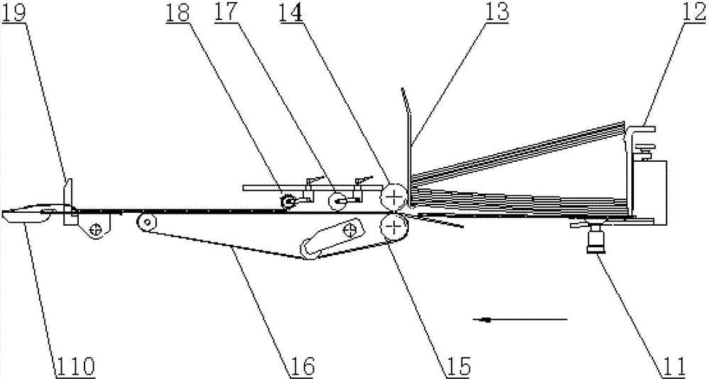
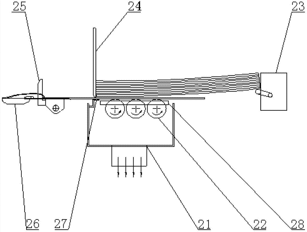
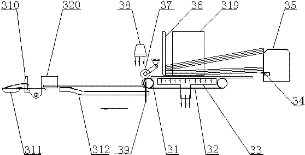
[0055] The positioning and conveying device for sheet-fed automatic die-cutting machine provided by the present invention, such as Figure 3 to Figure 5 As shown, it includes paper storage mechanism, paper feeding mechanism, paper pushing mechanism and positioning mechanism.

[0056] The paper storage mechanism includes a rear paper support frame 35 , a front baffle 36 and a side baffle 319 , the rear paper support 35 is provided with an outstretched rear support 34 , and the side baffle 319 and the front baffle 36 are perpendicular to each other.

[0057] The paper feeding mechanism includes a suction box 33, a first driving mechanism and at least one group of belt transmission mechanisms. In this embodiment, three groups of belt transmission mechanisms are used, and each group of belt transmission mechanisms includes a conveyor belt...


PUM


Abstract

The invention discloses a device and a method for positioning and conveying of an automatic sheet-fed die-cutting machine. The device comprises a paper storage mechanism, a paper feed mechanism, a paper pushing mechanism and a positioning mechanism. The paper feed mechanism comprises an air suction box, a first drive mechanism and at least one belt drive mechanism group, each belt drive mechanism group comprises a conveying belt power roller, a conveying belt driven roller and an air suction conveying belt with uniformly distributed air suction holes, the air suction box is positioned between the upper layer and the lower layer of each air suction conveying belt, and a gap for a sheet to pass through is reserved between the upper surface of each air suction conveying belt and the lower end of a front retaining plate. The paper pushing mechanism comprises at least one paper support plate, at least two pushing handles and second drive mechanisms, and each pushing handle reciprocates along the direction perpendicular to the axis of each conveying belt power roller under the action of the corresponding second drive mechanism. The positioning mechanism comprises at least two front guides and two side guides, and each front guide corresponds to an inductive switch and one second drive mechanism set. Determinacy positioning of paperboards at a controllable state is achieved in the condition of poor flatness of the paperboards.

Description

technical field [0001] The invention relates to post-press mechanical equipment and an automatic die-cutting machine, and specifically belongs to a positioning and conveying device and method for an automatic die-cutting machine for sheet-fed paper (including cardboard, corrugated paper, etc.). Background technique [0002] When the sheet-fed automatic die-cutting machine is working, it needs to transport the processed materials such as paper, cardboard and so on to the positioning and biting position of the automatic die-cutting machine through a special paper feeding mechanism or device, so that the gripper bar can hold the paper or Cardboard, etc. enter the die-cutting processing station for processing. At present, there are mainly two types of paper feeding mechanisms used in domestic automatic sheet-fed cardboard and corrugated paper die-cutting machines, namely, suction cup-type paper-feeding mechanisms and leading edge-type paper-feeding mechanisms. [0003] figure ...

Claims


Application Information

Patent Timeline
Patent Type & Authority Applications(China)
IPC IPC(8): B65H3/12B65H3/48B65H5/16B65H5/04B65H9/00
Inventor 李宁刘传喜
Owner SHANGHAI YOCO PRINTING MACHINERY
Why Eureka
Try Eureka