

Detection method and device of internal leakage of hydraulic valve
A detection method and detection device technology, applied in the field of leak detection, can solve problems such as difficult maintenance and replacement, leakage of the test system, poor anti-pollution ability, etc., and achieve the effect of fast detection, high precision and low cost
- Summary
- Abstract
- Description
- Claims
- Application Information
AI Technical Summary
Problems solved by technology
Method used
Image

Examples
Embodiment 1
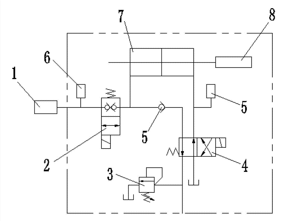
[0026] A method for detecting internal leakage of a hydraulic valve, using a combination of a hydraulic cylinder 7 and a displacement sensor 8, the hydraulic cylinder 7 and the hydraulic valve 1 to be tested are connected to a test pipeline, and the displacement of the piston of the hydraulic cylinder 7 is converted to calculate a section The leakage of the hydraulic valve 1 under test within a certain period of time is used to detect the leakage in the hydraulic valve.
[0027] When detecting the displacement of the piston of the hydraulic cylinder 7, it is calculated by using a computer to collect the signals of the displacement sensor 8 through the board. After calculating and detecting the displacement of the piston of the hydraulic cylinder 7, the signal of the pressure sensor 6 installed in the test pipeline is collected at the same time, and the curve of the leakage of the tested hydraulic valve 1 under a certain pressure is drawn through calculation.
Embodiment 2
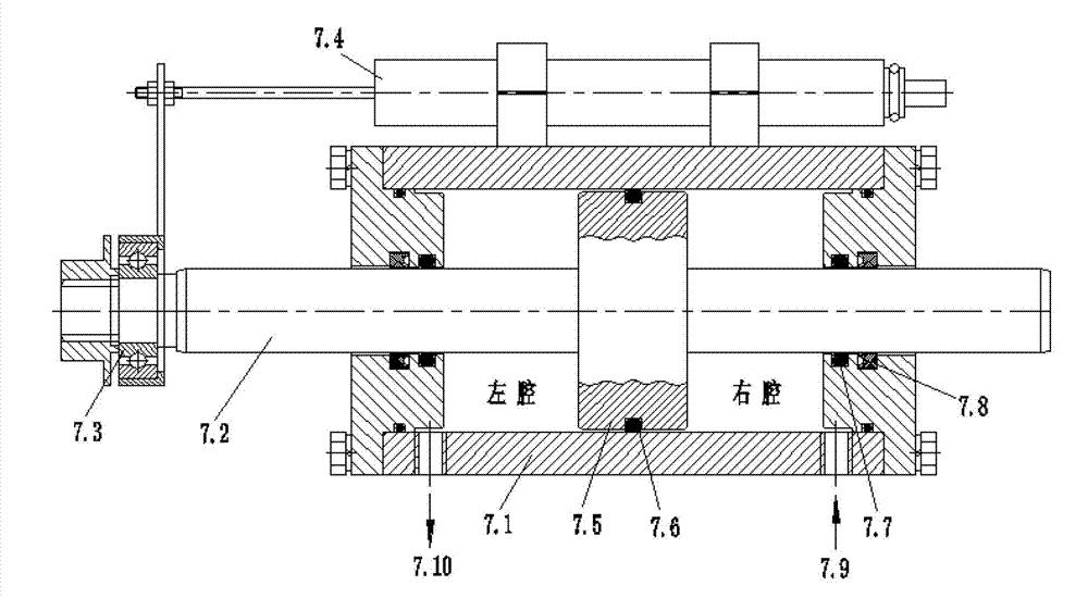
[0029] A detection device for internal leakage of a hydraulic valve, including a test bench, a double one-way electromagnetic reversing valve 2, an electromagnetic reversing valve 4 and a hydraulic cylinder 7, and a test pipeline connected to the double one-way electromagnetic reversing valve on the test bench 2, the electromagnetic reversing valve 4, and the hydraulic cylinder 7 are connected to the test pipeline, the displacement sensor 8 is installed above the cylinder barrel of the hydraulic cylinder 7, and the sensing rod of the displacement sensor is connected to the piston rod of the hydraulic cylinder 7. The test pipeline is equipped with a one-way valve 5 and a relief valve 3. The test pipeline is provided with the hydraulic valve 1 interface to be tested.
[0030] The test pipeline is equipped with a pressure sensor 6, and the pressure sensor 6 and the displacement sensor 8 are connected to the computer.
[0031] The principle of this embodiment and the concrete str...
PUM
 Abstract
Description
Claims
Application Information