A spray mass transfer condenser

A technology of condenser and condenser tube, applied in the direction of evaporator/condenser, steam/steam condenser, refrigerator, etc., can solve the problems of large water transportation, poor vacuum effect, high energy consumption, and prevent the inner film of the tube. Condensation, saving energy consumption, improving the effect of heat transfer coefficient

Active Publication Date: 2015-08-12
FOSHAN DEZHONG PHARMA MACHINERY
View PDF6 Cites 2 Cited by
  • Summary
  • Abstract
  • Description
  • Claims
  • Application Information

AI Technical Summary

Problems solved by technology

The characteristics of traditional condensers in various ways are: large area, large water transportation volume, high energy consumption, poor vacuum effect, etc.

Method used


Image

  • A spray mass transfer condenser
  • A spray mass transfer condenser
  • A spray mass transfer condenser

Examples


Embodiment Construction

[0010] Embodiments of the present invention will now be described with reference to the drawings, in which like reference numerals represent like elements.

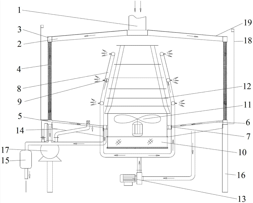
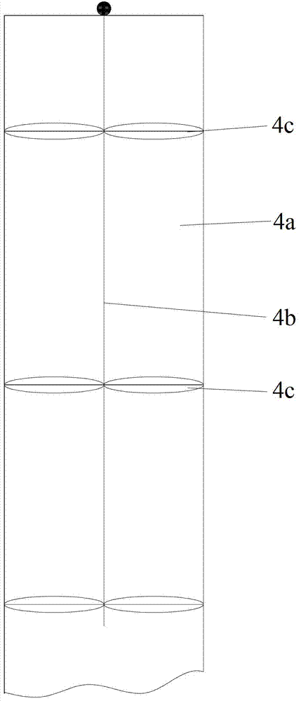
[0011] Please refer to Figure 1-3 , the spray mass transfer condenser includes a secondary steam main pipe 1, a secondary steam distribution pipe 2, an upper ring 3, a plurality of vertically arranged finned condenser tubes 4 connected in a ring, a middle ring 5, an oblique row Pipe 6, bottom ring 7, circular spray pipe 8, atomizing nozzle 9, protective net 10, fan 11, air distributor 12, spray pump 13, water collecting tray 14, vapor-liquid separator 15, support Foot 16, water ring pump 17, casing 18 and top cover 19.

[0012] The secondary steam distribution pipe 2 is connected to the secondary steam main pipe 1; the upper ring 3 is connected to the secondary steam distribution pipe 2; 4 is connected to the upper ring 3; the middle ring 5 is connected to the finned condensation pipe 4; the slanted tube 6 is connected...


PUM


Abstract

The invention discloses a spraying mass transfer type condenser. The condenser comprises a plurality of finned condensing tubes, a water collecting disk and a fan, wherein the plurality of finned condensing tubes are distributed in a circular shape, the water collecting disk is arranged below finned condensing tubes, a secondary steam header pipe is connected above finned condensing tubes, spraying pipes which are distributed in a circular shape are arranged inside the plurality of finned condensing tubes which are distributed in a circular shape, and atomizing nozzles are arranged on spraying pipes. The spraying mass transfer type condenser atomizes water through atomizing nozzles, sprays the water to surfaces of finned condensing tubes for heat absorption and evaporates the water. By the aid of the convective heat transfer having phase changes, the heat exchange coefficient is greatly improved, the condensing energy consumption is greatly saved, besides, the secondary steam header pipe is located above finned condensing tubes, so that the direction of high-speed steam is consistent with the direction of condensed water, the film condensation inside tubes can be prevented effectively, and the heat transfer coefficient is improved.

Description

technical field [0001] The invention belongs to a condensation device, in particular to a spray mass transfer condenser of a vacuum concentration device. Background technique [0002] At present, the condensing part of domestic vacuum concentration equipment generally adopts tube condensers, mixers or hydraulic ejectors. All methods use single-phase fluid heat transfer with cooling water as the heat carrier, that is, the cooling water does not undergo phase change during the cooling process, the amount of water transported during the condensation process is large, the power of the circulating pump is large, and all The form must be equipped with a cooling tower, and the water cooled by the cooling tower is sent to the condenser again. The characteristics of various traditional condensers are: large area, large water transportation volume, high energy consumption, poor vacuum effect, etc. Contents of the invention [0003] The object of the present invention is to provide...

Claims


Application Information

Patent Timeline
Patent Type & Authority Patents(China)
IPC IPC(8): F25B39/04F28B1/02F28B9/00
Inventor 杨许作
Owner FOSHAN DEZHONG PHARMA MACHINERY
Why Eureka
Try Eureka