Simulation method for rectangular ultrasonic transducer sound field

An ultrasonic transducer and sound field simulation technology, which is applied in the fields of instruments, special data processing applications, electrical digital data processing, etc., can solve the problems of complex simulation process, low simulation efficiency, and complex simulation.

Active Publication Date: 2013-01-09
云南保利天同水下装备科技有限公司
View PDF4 Cites 8 Cited by
  • Summary
  • Abstract
  • Description
  • Claims
  • Application Information

AI Technical Summary

Problems solved by technology

In the prior art, in order to obtain the sound pressure distribution of the ultrasonic transducer, measurement methods are mainly used, such as radiation force method, hydrophone method, optical fiber detection method and ball reflection method, etc. These measurement methods need to be designed and After the sample is processed and manufactured, the actual object can be used for measurement, and no matter which measurement method requires professional instruments and equipment, it consumes a lot of manpower and material resources
In order to solve these problems, some researchers began to study the sound field simulation method of ultrasonic transducers. For circular ultrasonic transducers, P.R.Stepanishen (Journal of the Acoustical Society) published in the 49th issue of the American Acoustic Society in 1971 of America), published the article "The time-dependent force and radiation impedance on a piston in a rigid infinite planar baffle" , a simulation model of spatial impulse response is proposed

Method used


Image

  • Simulation method for rectangular ultrasonic transducer sound field
  • Simulation method for rectangular ultrasonic transducer sound field
  • Simulation method for rectangular ultrasonic transducer sound field

Examples


Embodiment Construction

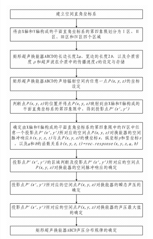
[0062] Such as figure 1 As shown, the rectangular ultrasonic transducer sound field simulation method of the present invention comprises the following steps:

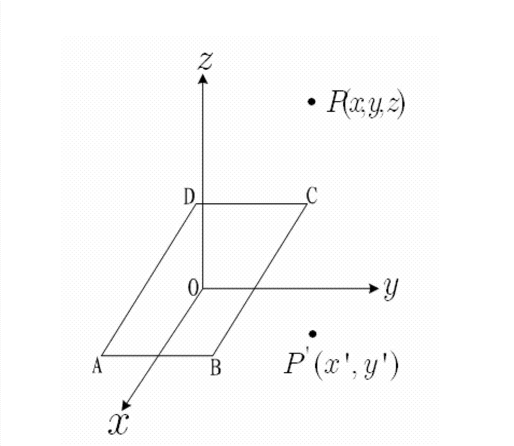
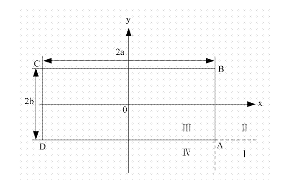
[0063]Step 1. Establish a spatial Cartesian coordinate system: take the center of the rectangular ultrasonic transducer ABCD as the coordinate point, and the straight line passing through the center of the rectangular ultrasonic transducer ABCD and parallel to the long sides BC and DA of the rectangular ultrasonic transducer ABCD is X-axis, the straight line passing through the center of the rectangular ultrasonic transducer ABCD and parallel to the broad sides AB and CD of the rectangular ultrasonic transducer ABCD is the Y-axis, passing through the center of the rectangular ultrasonic transducer ABCD and perpendicular to the rectangular ultrasonic transducer The straight line of the plane where ABCD is located is the Z axis, and a space Cartesian coordinate system is established; wherein, the vertex A of the rectangul...


PUM


Abstract

The invention discloses a simulation method for a rectangular ultrasonic transducer sound field. The simulation method includes the following steps of 1, establishing a space rectangular coordinate system; 2, regionalizing a fourth quadrant; and 3, simulating a sound field of a rectangular ultrasonic transducer under a simulation software environment by a computer. Specifically, 301, setting and storing initial parameters; 302, setting a coordinate of an arbitrary point P (x,y,z) in sound field radiation space, 303, judging and mapping the position of the point P (x,y,z), 304, determining function relationship h (x,y,z,t)=rec_response (x,y,z,a,b), 305, determining space pulse response h (x,y,z,t) of the transducer by the space point P (x,y,z), 306, determining transient sound pressure p (x,y,z,t) of the transducer by the space point P (x,y,z), 307, determining sound pressure maximum pmax (x,y,z) of the transducer by the space point P (x,y,z), and 308, determining sound pressure distribution rule of the rectangular ultrasonic transducer. The simulation method for the rectangular ultrasonic transducer sound field is novel and reasonable in design, convenient to be realized, low in cost, high in simulation efficiency and high in accuracy, provides theoretical basis for optimizing the design of the rectangular transducer and making nondestructive testing process, and is high in practicability.

Description

technical field [0001] The invention relates to the technical field of sound field characteristics research of ultrasonic transducers, in particular to a sound field simulation method of a rectangular ultrasonic transducer. Background technique [0002] Ultrasonic transducers are often used in industrial nondestructive testing. The performance of ultrasonic transducers plays a very important role in industrial nondestructive testing. The sound pressure distribution characteristics of the sound field are one of the important performances of ultrasonic transducers. The resolution, positioning and size judgment of defect detection have a great influence. Therefore, in the process of designing and selecting ultrasonic transducers before use, it is necessary to know in advance the spatial distribution of the ultrasonic transducer's radiated sound field, including the length of the near-field region and the sound pressure distribution on the sound axis. In the prior art, in order...

Claims


Application Information

Patent Timeline
IPC IPC(8): G06F17/50
Inventor 马宏伟董明陈渊毛清华齐爱玲
Owner 云南保利天同水下装备科技有限公司
Why Eureka
Try Eureka