
Electrode structure and electrode fixing structure for plasma thruster

A technology of electrode structure and plasma, applied in the direction of using plasma, plasma, electrical components, etc., can solve the problems of increasing the resistance of the main discharge circuit, reducing the discharge current, and affecting the electromagnetic acceleration effect and thrust effect of the pulse plasma thruster. , to achieve the effect of improving the thrust effect, reducing local loss and improving work efficiency

Active Publication Date: 2013-01-09
BEIJING JIAOTONG UNIV
View PDF10 Cites 23 Cited by
  • Summary
  • Abstract
  • Description
  • Claims
  • Application Information

AI Technical Summary

Problems solved by technology

However, both patents set the insulating ceramic nozzle on the metal electrode, which will increase the resistance of the main discharge circuit and reduce the discharge current under the same discharge energy, thus affecting the electromagnetic acceleration and thrust effects of the pulsed plasma thruster

Method used


Image

  • Electrode structure and electrode fixing structure for plasma thruster
  • Electrode structure and electrode fixing structure for plasma thruster
  • Electrode structure and electrode fixing structure for plasma thruster

Examples


Embodiment Construction

[0027] In order to make the above objects, features and advantages of the present invention more comprehensible, the present invention will be further described in detail below in conjunction with the accompanying drawings and specific embodiments.

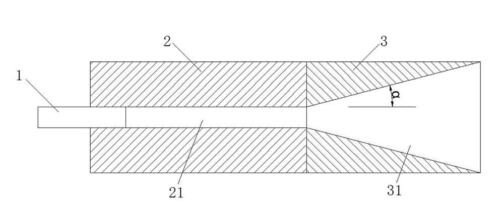
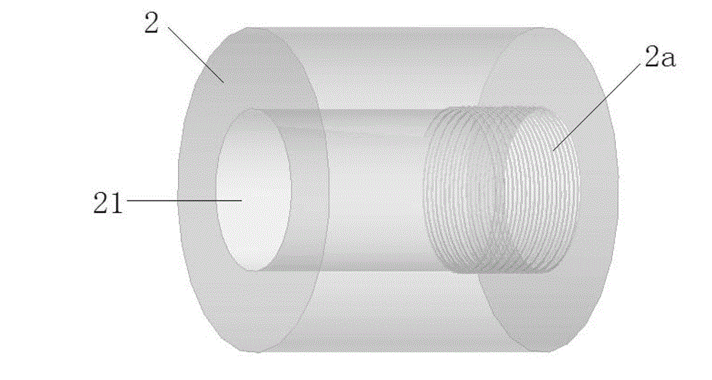
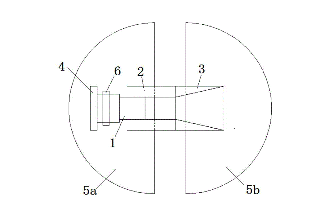
[0028] figure 1 It is a schematic diagram of the electrode structure of the present invention. In this embodiment, it includes: a cylindrical cathode 1, a cylindrical insulator 2, and an anode 3, wherein the cylindrical cathode 1 has a diameter of 5 mm and a length of 10 mm. The material of the cathode can be lead or Aluminum and other metals. One end of the cylindrical cathode 1 is inserted into the interior of the cylindrical insulator 2 with a through hole 21 and is in close contact with it, and the distance from the cylindrical cathode 1 into the interior of the cylindrical insulator 2 is adjustable, but the cylindrical cathode 1 should be ensured The contact position between the front end surface and the inner through hole 2...


PUM


Abstract

The invention discloses an electrode structure for a plasma thruster. The electrode structure comprises a cathode and an anode, wherein the cathode is a cylindrical cathode, one end of the cathode is inserted into a tube-shaped insulator with a through hole, the other end of the insulator is provided with the anode, a hollow cavity is arranged in the anode in a same axial direction with the through hole of the tube-shaped insulator, the sectional area of the cavity is progressively increased along the axial extension direction of the tube-shaped insulator, and threads are arranged on the inner surface of the tube-shaped insulator and are single threads, double threads or multiple threads. According to the electrode structure disclosed by the invention, through a reasonable electrode structure design, better electric heating acceleration effect is obtained by utilizing the aerodynamic force generated due to difference of pressures insides and outsides a tube after discharging, thus effectively improving the thrusting effect and the working efficiency of the pulse plasma thruster. With the adoption of the electrode structure, the thrusting effect is good, and a plasma obtained after discharging is large in density and has a simple structure.

Description

technical field [0001] The invention belongs to the technical field of electric propulsion applied to microsatellites, relates to an electrode structure for a plasma thruster, and more specifically relates to a pulsed plasma thruster which uses the electrode structure to discharge the inner surface of a cylinder. Background technique [0002] For space propulsion systems, chemical propulsion systems and electric propulsion systems are currently being studied more. Traditional chemical mission propulsion systems are applied to micro-satellites, which have large mass and volume, small specific impulse, and complex structure, which greatly limit its application on micro-satellites, and various types of electric propulsion systems can just make up for this deficiency. It is an ideal choice for micro-satellite propulsion system. Among many electric propulsion systems, the pulsed plasma thruster is a small-thrust electromagnetic thruster, which has the advantages of high specific...

Claims


Application Information

Patent Timeline
IPC IPC(8): H05H1/34F03H1/00
Inventor 刘文正张德金王浩
Owner BEIJING JIAOTONG UNIV
Learn More