Stents for prosthetic heart valves

A valve and prosthesis technology, which is applied in the field of percutaneously implanted prosthetic heart valves, can solve the problems of high invasiveness of valve surgery, and achieve the effect of minimizing tissue pressure and reducing crown density

Inactive Publication Date: 2013-01-09
MEDTRONIC INC
View PDF17 Cites 76 Cited by
  • Summary
  • Abstract
  • Description
  • Claims
  • Application Information

AI Technical Summary

Problems solved by technology

This type of valve surgery is highly invasive and exposes the patient to potentially serious risks such as infection, stroke, kidney failure and adverse effects associated with, for example, the use of a heart-lung bypass machine

Method used


Image

  • Stents for prosthetic heart valves
  • Stents for prosthetic heart valves
  • Stents for prosthetic heart valves

Examples


Embodiment Construction

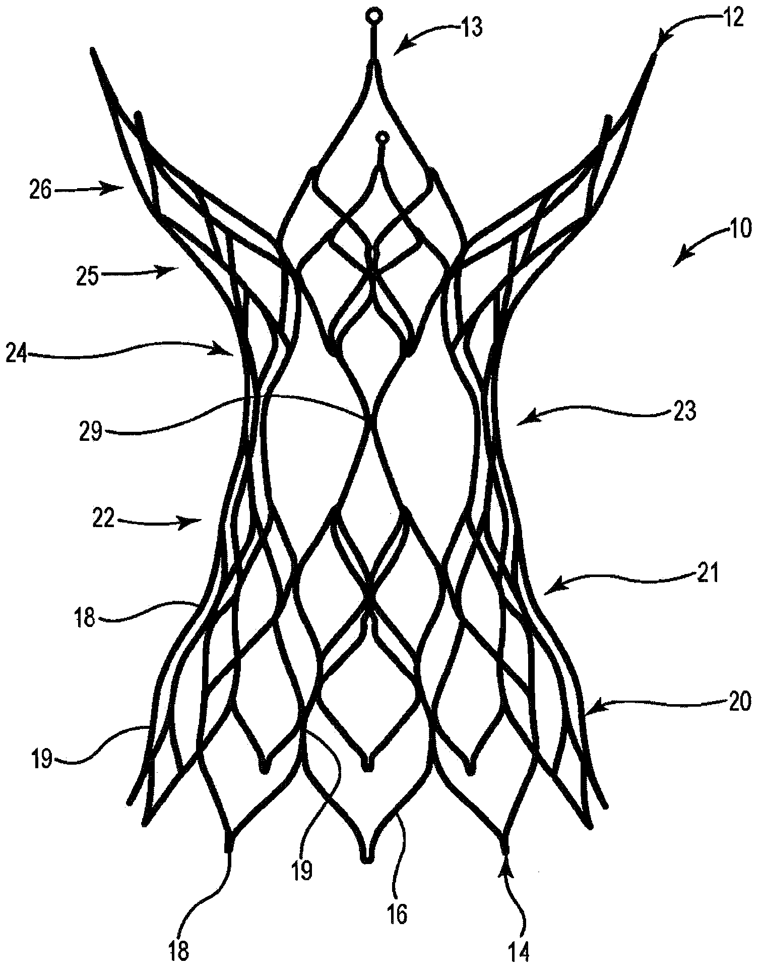
[0038] As mentioned herein, prosthetic heart valves used in various devices and methods of heart valve delivery can include a variety of different configurations, such as prosthetic heart valves with tissue leaflets or with polymer, metal, or tissue Synthetic heart valve with designed leaflets and can be specially constructed to replace any heart valve. Furthermore, while much of the description herein refers to replacement of the aortic valve, the prosthetic heart valve of the present invention may also be used in general to replace the native mitral, pulmonary, or tricuspid valve, as a venous valve, or to replace a valve such as Failed bioprostheses in areas such as the aortic valve or mitral valve.

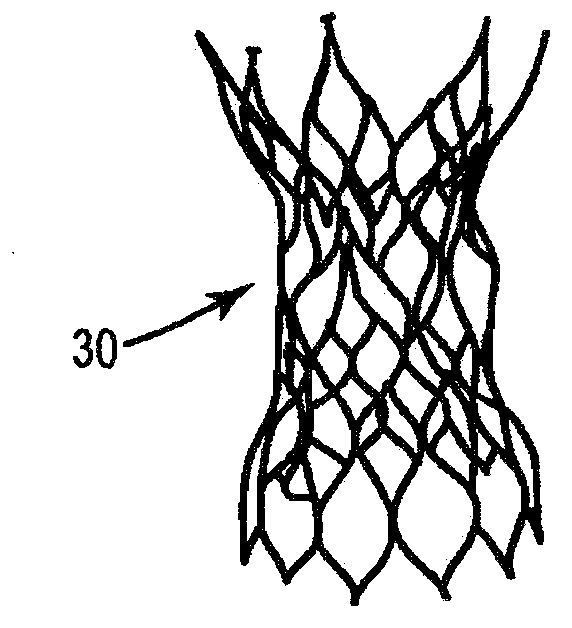
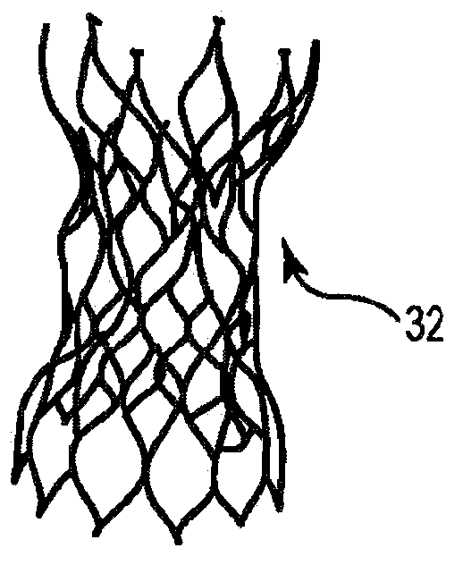
[0039] While each stent described herein generally includes leaflets attached within the inner stent region, for clarity the leaflets are not shown in most of the illustrated embodiments. In general, the stents described herein include a support structure that includes a plura...


PUM


Abstract

A prosthetic valve including a wire frame having a generally tubular body portion, an interior area, a longitudinal axis, a first end comprising a plurality of crowns, and a second end comprising a greater number of crowns than the first end. The wire frame includes a plurality of adjacent rows of modified diamond-shaped structures extending between the first and second ends. The prosthetic valve further includes a valve structure that includes a plurality of leaflets and that is attached within the interior area of the wire frame.

Description

[0001] priority claim [0002] This application claims the benefit of US Provisional Patent Application No. 61 / 317,459, filed March 25, 2005, entitled "STENTS FOR PROSTHETIC HEART VALVES," which is incorporated herein by reference in its entirety. technical field [0003] The present invention relates to prosthetic heart valves. More specifically, the present invention relates to devices, methods and delivery systems for percutaneous implantation of prosthetic heart valves. Background technique [0004] Diseased or otherwise defective heart valves can be repaired or replaced using a variety of different types of heart valve surgery. Typical heart valve surgery involves open heart surgery under general anesthesia, during which the heart is stopped and blood flow is controlled by a heart-lung bypass machine. This type of valve surgery is highly invasive and exposes the patient to potentially serious risks such as infection, stroke, kidney failure and adverse effects associa...

Claims


Application Information

Patent Timeline
Patent Type & Authority Applications(China)
IPC IPC(8): A61F2/24
CPCA61F2230/0078A61F2230/0054A61F2250/0036A61F2230/0067A61F2/2418A61F2230/008A61F2/2412A61F2220/0075A61F2250/0039A61F2/2433
Inventor G·M·佩里格里尼M·克里沃鲁奇科F·O·林纳M·J·拉斯特
Owner MEDTRONIC INC
Why Eureka
Try Eureka