
Sucking circulating belt type filtering device

A technology of filter device and circulating belt, applied in the direction of filtration and separation, moving filter element filter, separation method, etc., can solve the problems of inconvenient maintenance, difficult disassembly, and inability to continuously circulate and filter, and achieve convenient maintenance, reduce losses, Simple to use effects

Active Publication Date: 2013-01-16
烟台开发区博森科技发展有限公司
View PDF6 Cites 8 Cited by
  • Summary
  • Abstract
  • Description
  • Claims
  • Application Information

AI Technical Summary

Problems solved by technology

The invention patent with the patent number ZL200610012906.0 discloses a belt-type pressurized filter device. The whole device includes the sealed pressurized chamber of the filter chamber and its internal equipment. filter

Method used


Image

  • Sucking circulating belt type filtering device
  • Sucking circulating belt type filtering device
  • Sucking circulating belt type filtering device

Examples


Embodiment Construction

[0029] The principles and features of the present invention are described below in conjunction with the accompanying drawings, and the examples given are only used to explain the present invention, and are not intended to limit the scope of the present invention.

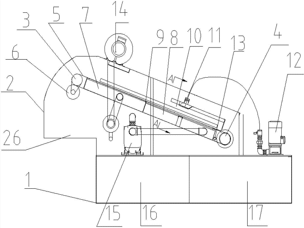
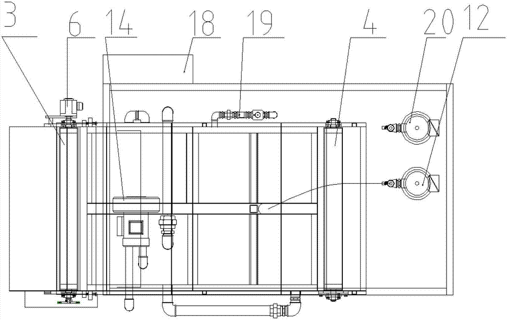
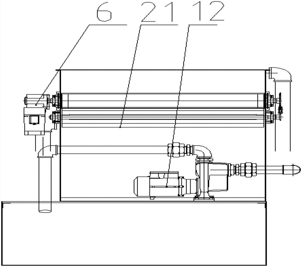
[0030] Such as Figure 1-Figure 3 As shown, the suction circulation belt filter device provided by the invention includes a liquid tank 1 and a housing 2, the housing 2 is fixed on the liquid tank 1, and a power roller 3 is fixed at one end in the housing 2, and the other One end is fixed with a driven roller 4, and the position of the power roller 3 in the housing 2 is higher than that of the driven roller 4, and the housing 2 under the power roller 3 is provided with a slag outlet 26. A cleaning brush 21 is installed under the power roller 3, and the cleaning brush 21 is in contact with the surface of the filter belt 5. The filter belt 5 is wound on the power roller 3 and the driven roller 4, and a control device...


PUM


Abstract

The invention relates to the technical field of cutting liquid filtering equipment, in particular to a sucking circulating belt type filtering device. The device comprises a liquid box and a shell, wherein the shell is fixed on the liquid box; a driving roller is fixed at one end in the shell, and a driven roller is fixed at the other end in the shell; a filtering belt winds the driving roller and the driven roller; a control device and a drive motor are arranged on the side of the shell; the control device is connected with the drive motor, and the drive motor is connected with the driving roller; the upper layer of the filtering belt, the lower layer of the filtering belt and two sides of the shell define a cavity; the cavity is divided into a drying cavity and a sucking cavity by a partition plate; a gap plate is arranged on the lower part of the upper layer of the filtering belt; a filtering cavity is formed on the lower half part of the upper layer of the filtering belt, and a waste liquid inlet is formed in the filtering cavity; and a sucking pump is fixed on the liquid box and connected to a sucking cavity through a pipeline, and a negative pressure message-sending device which is arranged on the side of the shell is connected to the sucking cavity. By the device, the cutting liquid can be effectively filtered, the using cost of a machine tool is reduced, and automatic filtering is realized; and the device is easy to operate and convenient to maintain.

Description

technical field [0001] The invention relates to the technical field of cutting fluid filtering equipment, in particular to a suction circulation belt filter device. Background technique [0002] At present, the cutting fluid filter devices mainly include gravity paper tape filter devices, vertical paper tape filter devices, negative pressure paper tape filter devices, and cloth bag filter devices. Each has different application fields, which can basically cover the existing main grinding debris processing, and can filter different materials such as cast iron chips, aluminum chips, steel chips, copper chips, etc., but the above filtering devices have certain deficiencies in the working process. A large amount of filter paper or non-woven fabric consumables will be consumed when filtering grinding debris, especially in the process of high-precision gear grinding machine tools, in order to ensure the machining accuracy of workpieces, relatively expensive oily cooling media will...

Claims


Application Information

Patent Timeline
IPC IPC(8): B01D33/044B01D33/46
Inventor 周博由春晖纪艳青李铁兵宋立国王涛
Owner 烟台开发区博森科技发展有限公司
Learn More