Device capable of changing straight reciprocating movement to continuous circular movement

A technology of linear reciprocating motion and circular motion, applied in the direction of transmission, belt/chain/gear, mechanical equipment, etc., can solve the problems of difficult manufacturing and high cost, and achieve the effects of reduced cost, reduced loss and convenient manufacturing

Inactive Publication Date: 2013-01-16
王琦
View PDF3 Cites 4 Cited by
  • Summary
  • Abstract
  • Description
  • Claims
  • Application Information

AI Technical Summary

Problems solved by technology

[0004] In addition, the crankshaft in the crankshaft linkage mechanism is difficult to manufacture due to the non-concentric shaft, and the cost is relatively high.

Method used


Image

  • Device capable of changing straight reciprocating movement to continuous circular movement
  • Device capable of changing straight reciprocating movement to continuous circular movement
  • Device capable of changing straight reciprocating movement to continuous circular movement

Examples


Embodiment Construction

[0022] The present invention will be further described below in conjunction with the embodiments and the accompanying drawings.

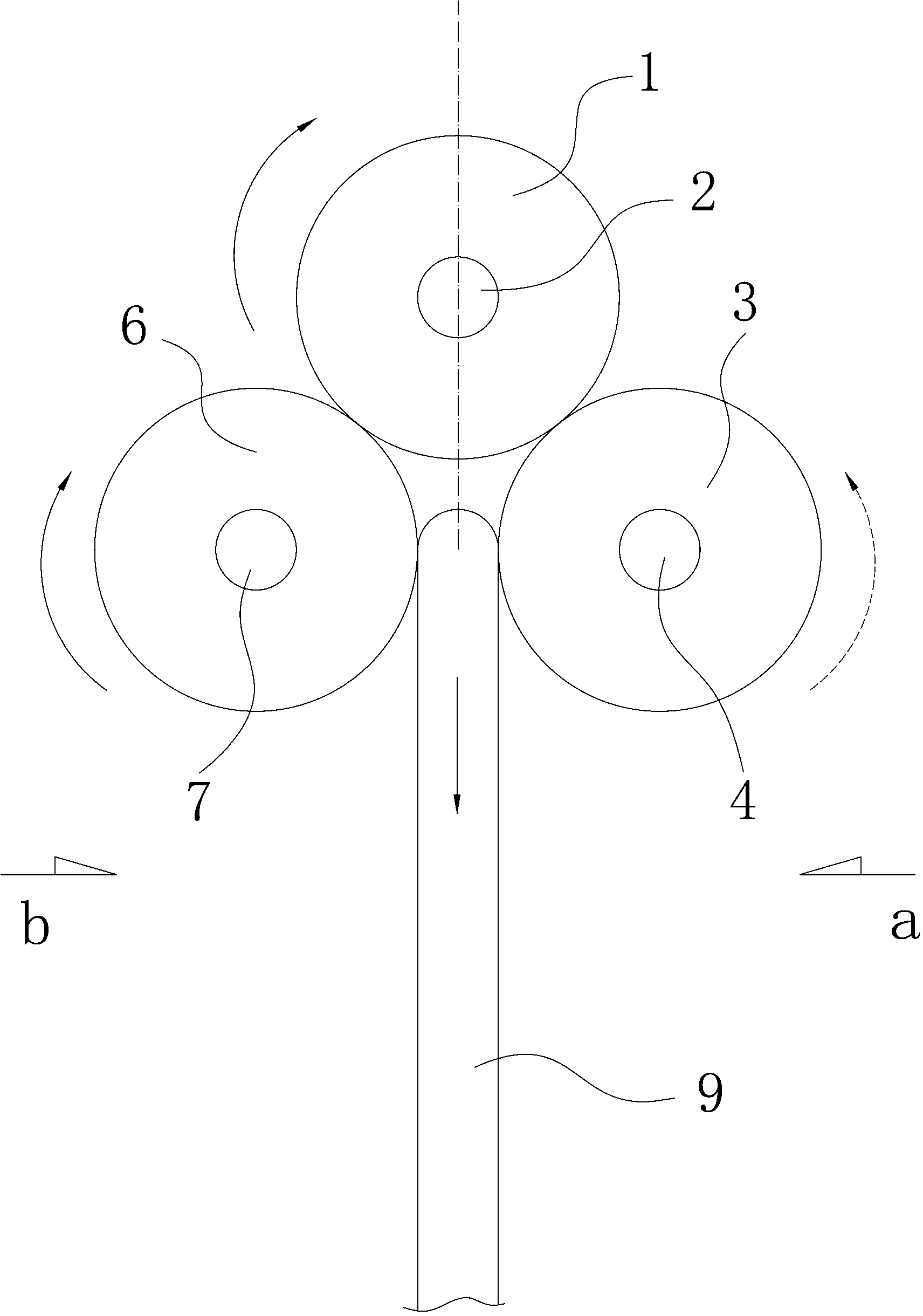
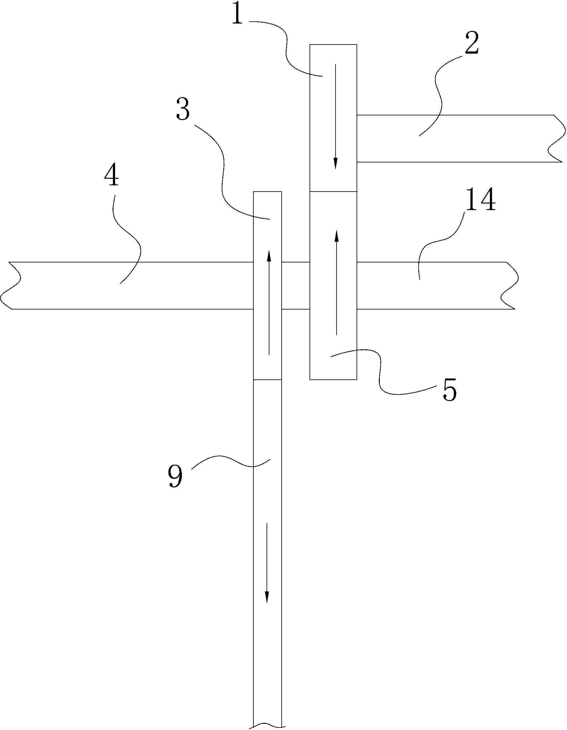
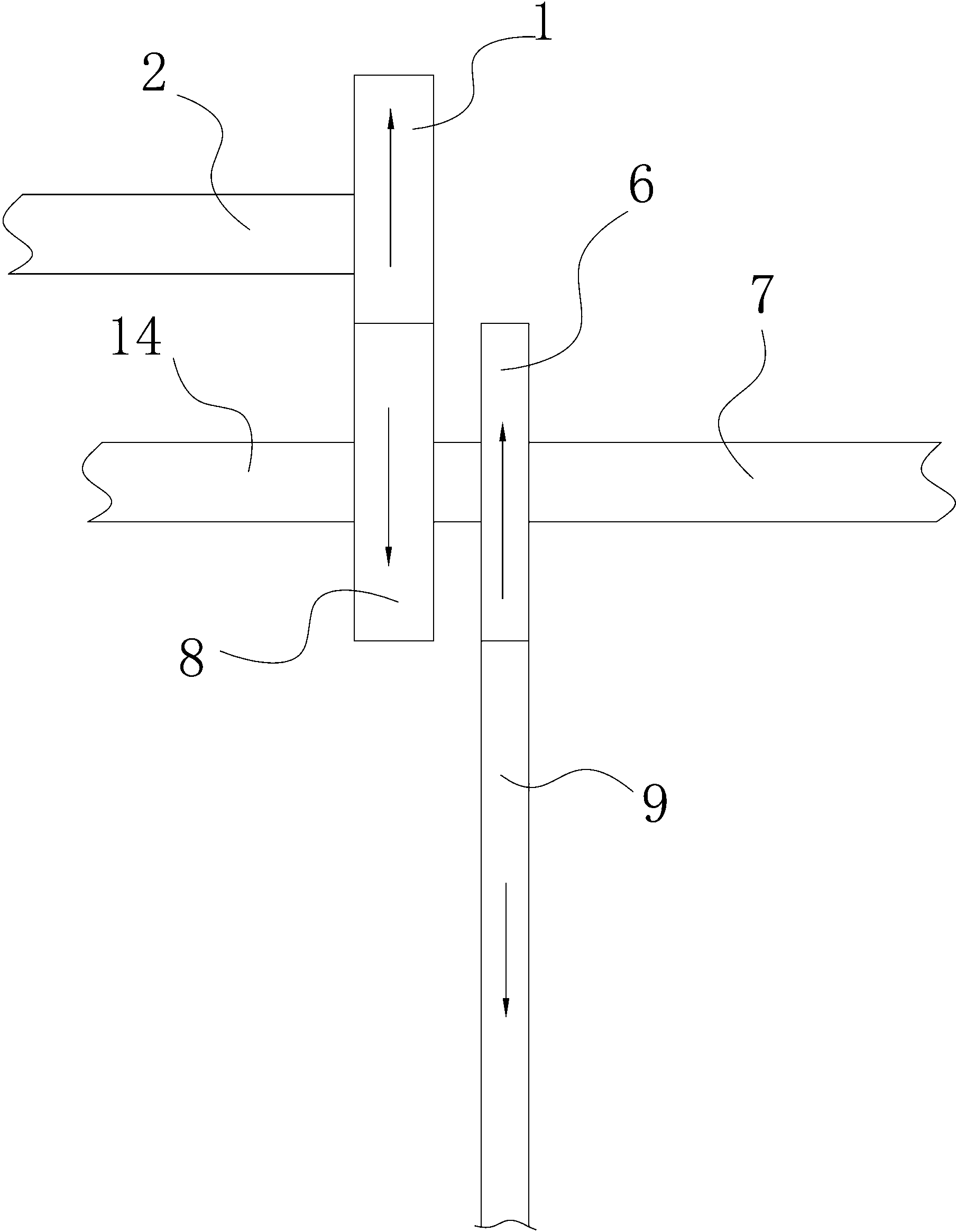
[0023] The invention includes a reciprocating rack and a gear meshed with the rack.

[0024] refer to figure 1 , figure 2 and image 3 , both sides of a reciprocating double-sided rack 9 of the present invention are respectively meshed with the first gear 3 and the second gear 6, the first gear 3 is fixedly connected with the first flywheel clutch 5 through the first transmission shaft 4, and the first gear 3 is fixedly connected with the first flywheel clutch 5. The outer peripheral gear of a flywheel clutch 5 meshes with the main shaft gear 1; the second gear 6 is fixedly connected with the second flywheel clutch 8 through the second transmission shaft 7 respectively, and the outer peripheral gear of the second flywheel clutch 8 also meshes with the main shaft gear 1 , Main shaft gear 1 is fixedly connected to main shaft 2.

[0025] refer to ...


PUM


Abstract

The present invention discloses a device capable of changing straight reciprocating movement to continuous circular movement. Two sides of a reciprocating two-sided rack or two single-sided racks reciprocating in the opposite directions are respectively engaged with a first gear and a second gear. The first gear and the second gear are fixedly connected with a first flywheel clutch and a second flywheel clutch respectively through a first transmission shaft and a second transmission shaft. An edge gear of the first flywheel clutch and an edge gear of the second flywheel clutch are engaged with a mainshaft gear at the same time. The device solves the problems of great loss of the kinetic energy caused by the pressure angle during the process of changing the straight reciprocating movement to the continuous circular movement in the prior art, namely, the problem of 30% of power loss of the crankshaft. In addition, a transmission gear is used to be coaxial with the flywheel clutch, so that the manufacturing is more convenient, and the manufacturing cost is greatly lowered. The flywheel clutch is a non-wear high-strength flywheel, so as to change the straight reciprocating movement to the continuous circular movement almost without loss during the transmitting movement.

Description

technical field [0001] The invention relates to a device for converting linear reciprocating motion into continuous circular motion, which is suitable for internal combustion engines or mechanisms driven by pressure to convert linear reciprocating motion into continuous circular motion. Background technique [0002] In the prior art, the transmission mechanism that converts linear reciprocating motion into continuous circular motion generally uses a crankshaft linkage mechanism for transmission. When this mechanism is in operation, the transmission force is greatly lost due to the pressure angle relationship. [0003] The force on the piston in the internal combustion engine cylinder is related to the ratio of the volume of the expanded gas to the cylinder space before doing work. When the piston is at the top dead center, its spatial volume base is the smallest, and a relatively small amount of expansion gas is required to obtain a large force; when the piston starts to mov...

Claims


Application Information

Patent Timeline
Patent Type & Authority Applications(China)
IPC IPC(8): F16H37/00
Inventor 王琦
Owner 王琦
Why Eureka
Try Eureka