Rear-placed combustor with annular porous medium head for ultramicro turbojet engine

A technology of turbojet engine and porous media, applied in combustion chambers, continuous combustion chambers, machines/engines, etc., can solve the problems of low combustion efficiency in combustion chambers, short residence time of gas, poor flame stability, etc., to achieve improved combustion efficiency, Overcoming the effect of short residence time and reducing heat loss

Active Publication Date: 2013-01-16
BEIHANG UNIV
View PDF4 Cites 16 Cited by
  • Summary
  • Abstract
  • Description
  • Claims
  • Application Information

AI Technical Summary

Problems solved by technology

[0005] The combustion chamber of the micro-turbojet engine is an important part of the super-micro-turbojet engine. Compared with the conventional combustion chamber, the heat loss of the super-micro-turbojet engine combustion chamber is high, and the gas residence time is short, which will lead to low combustion efficiency in the combustion chamber and flame Poor stability
According to the open literature at hand, the design of the combustion chamber of the ultra-micro turbojet engine currently under development has not solved these problems well.

Method used


Image

  • Rear-placed combustor with annular porous medium head for ultramicro turbojet engine
  • Rear-placed combustor with annular porous medium head for ultramicro turbojet engine
  • Rear-placed combustor with annular porous medium head for ultramicro turbojet engine

Examples


Embodiment Construction

[0030]The present invention will be described in detail below in conjunction with the accompanying drawings and specific embodiments.

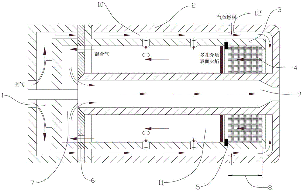
[0031] like figure 1 As shown, the ultra-micro turbojet engine combustion chamber of the annular porous medium head of the embodiment of the present invention adopts acetylene as gas fuel, and consists of the combustion chamber casing 2, the flame tube wall 3, the combustion chamber outlet 6 and the annular porous medium head Combustion chamber casing 2, flame tube wall 3 and combustion chamber outlet 6 are sintered with alumina ceramic material.

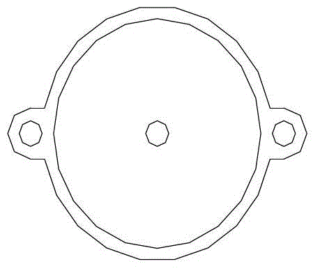
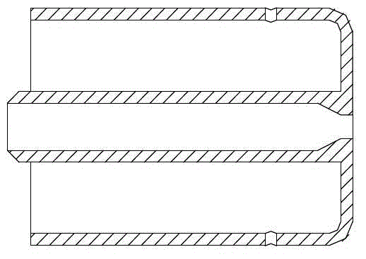
[0032] like Figure 2a , Figure 2b , Figure 2c As shown, the combustor case 2 includes two parts, the outer ring and the inner ring, and the space contained in the inner ring of the combustor case 2 is the exhaust passage 9; Flame cylinder wall 3, the structure is as Figure 3a , Figure 3b , as shown, between the flame tube wall 3 and the outer ring of the combustion chamber casing 2 is an ...


PUM


Abstract

Disclosed is a rear-placed combustor with an annular porous medium head for an ultramicro turbojet engine. An annular reflux structure is adopted for the combustor which is formed by a combustor box, a flame tube wall, a combustor outlet and the annular porous medium head. Air flow passes through a centrifugal compressor of the engine for compression, enters an annular cavity channel of the combustor, and then is mixed with gas fuel which is jetted in horizontally; premixed gas is pre-heated through the flame tube wall and then flows back to enter a flame tube through the annular porous medium head, and stable ignition is achieved; the whole mixed gas combustion process is finished in the flame tube, and high-temperature gas is discharged from the outlet of the rear-placed combustor; and then the high-temperature gas is discharged into air through a tail pipe after turbine blades of an impact engine does work. The combustor box, the flame tube wall and the combustor outlet are connected through bolts with high temperature glue sprayed on annular edges to guarantee the sealing. According to the combustor, features and advantages of stable flame of the annular porous medium head can be adapted to and played to the greatest extent, proneness to flameout of ultramicro combustors can be improved, so that the combustor can work for the ultramicro turbojet engine reliably and stably.

Description

technical field [0001] The invention relates to a combustion chamber of a gas turbine, in particular to a combustion chamber of an ultramicro turbojet engine. Background technique [0002] With the development of MEMS technology, it is possible to realize the development of ultra-micro-turbojet engine. This kind of power device has the characteristics of small size, light weight and high power density, and it will have great application prospects in micro-aircraft. [0003] The application prospect of micro-aircraft in military and civilian aspects has attracted people's attention day by day. In terms of military affairs, micro-aircraft can be equipped to platoon-level soldiers for low-altitude military reconnaissance, surveillance, and battlefield damage assessment; as anti-radiation and micro-attack weapons, they can destroy electronic facilities such as enemy radars and carry micro-warheads for attacks; For target search and communication relay; for biochemical detection...

Claims


Application Information

Patent Timeline
Patent Type & Authority Applications(China)
IPC IPC(8): F23R3/52F02C3/14
Inventor 林宇震林培华张弛张龙
Owner BEIHANG UNIV
Why Eureka
Try Eureka