Non-metallic O-shaped ring performance testing device

A test device, non-metallic technology, applied in the field of non-metallic O-ring performance testing, can solve the problems of sealing performance affecting the overall sealing performance, imprecise, difficult O-ring friction performance, sealing performance and stress relaxation performance, etc., to achieve The loading process is stable, the economy is good, and the effect of easy replacement

Active Publication Date: 2014-11-12
南京翔瑞智能装备技术股份有限公司
View PDF6 Cites 0 Cited by
  • Summary
  • Abstract
  • Description
  • Claims
  • Application Information

AI Technical Summary

Problems solved by technology

Its shortcomings are mainly manifested in: (1) During the medium loading process, the medium pressure acting in the medium chamber will affect the initial sealing specific pressure of the tested O-ring; (2) Failure to reflect the dynamic and static ring wear The sealing performance of the O-ring for the rear moving ring and the O-ring for the static ring in the state of stress relaxation; (3) The axial load loading of the O-ring is not stable and accurate; (4) It is difficult to install a The testing machine completes the testing of the friction performance, sealing performance and stress relaxation performance of the O-ring
[0005] O-rings for dynamic and static rings are auxiliary seals for mechanical seals, and their working conditions are similar to static seals, but their friction performance reflects the followability of the compensation ring, and their sealing performance directly affects the overall sealing performance of mechanical seals; dynamic and static rings The stress state and motion state of the O-ring have their own characteristics. The O-rings of the static ring and the static ring seat are pressed on all sides, and the O-ring between the moving ring and the shaft (or sleeve) follows the moving ring. There is fretting

Method used


Image

  • Non-metallic O-shaped ring performance testing device
  • Non-metallic O-shaped ring performance testing device
  • Non-metallic O-shaped ring performance testing device

Examples


Embodiment Construction

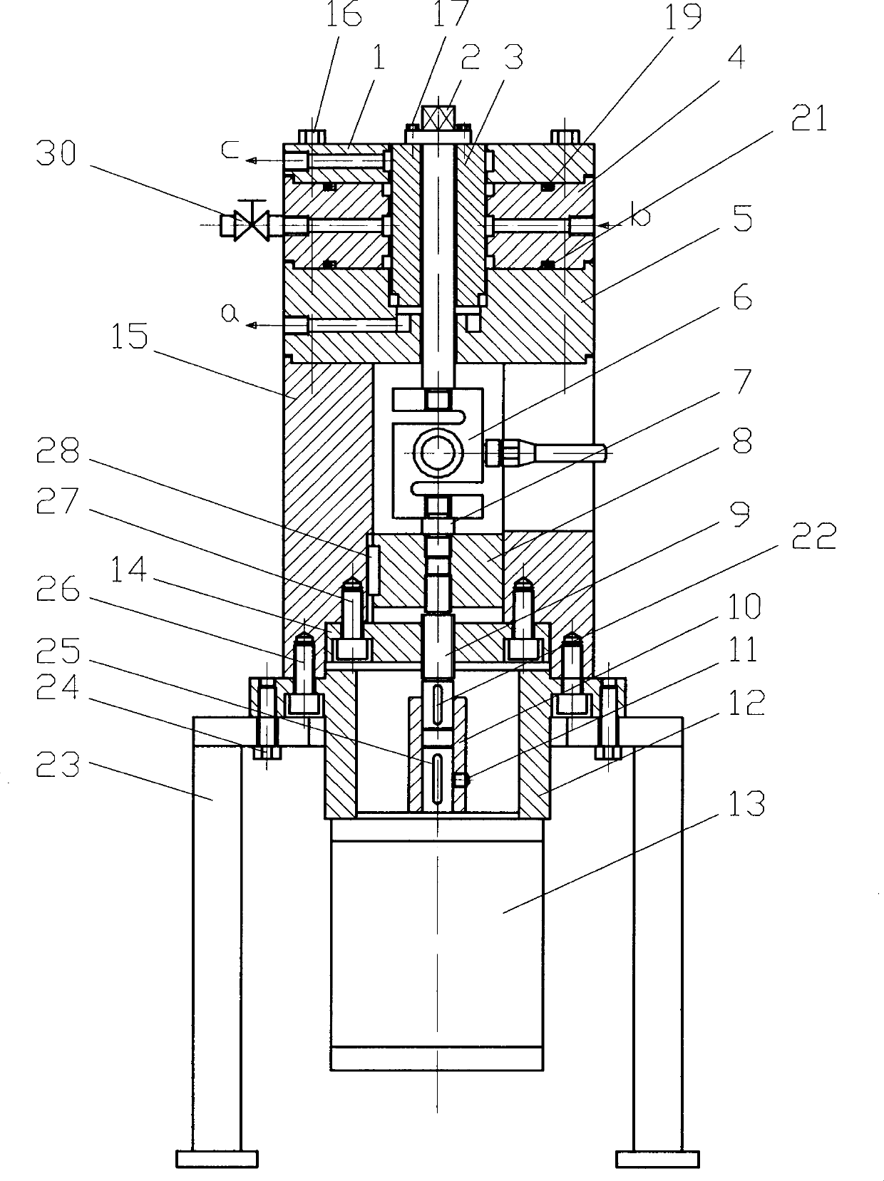
[0032] In order to further understand the invention content, characteristics and effects of the present invention, the following examples are given, and detailed descriptions are as follows in conjunction with the accompanying drawings:

[0033] figure 1 It is a schematic diagram of a non-metallic O-ring performance test device. The non-metallic O-ring performance test device consists of upper ring 1, through-center rod 2, mandrel 3, middle ring 4, lower ring 5, force sensor 6, connecting rod 7, nut I8, differential screw 9, sleeve coupling Device 10, set screw 11, flange bracket 12, stepper motor 13, nut II14, cylindrical bracket 15, bolt I16, bolt II17, O-ring II19, O-ring IV21, guide flat key I22, four-legged bracket 23. Bolt III24, key 25, bolt IV26, bolt V27, guide flat key II28, O-ring V29, stop valve 30 and other parts, the upper ring 1 and the lower ring 4 respectively have leak detection port Ic and leak detection port IIa, There are two radial circular through-hol...


PUM


Abstract

The invention relates to a non-metallic O-shaped ring performance testing device which is capable of testing friction performance and stress relaxation performance of O-shaped rings and sealing performance of O-shaped rings for static rings and moving rings of mechanical seals. The non-metallic O-shaped ring performance testing device comprises an upper ring, a through pull rod, a mandrel, a middle ring, a lower ring, a force sensor, a connecting pull rod, a nut I, a differential screw, a drive bush, set screws, a flange support, a stepping motor, a nut II, a cylindrical support, a bolt I, a bolt II, an O-shaped ring II, an O-shaped ring IV, a guide flat key I, a four-leg support, a bolt III, a key, a bolt IV, a bolt V, a guide flat key II, an O-shaped ring V and a stop valve. O-shaped ring grooves are arranged on the middle ring of the device, so that affection on initial sealing pressure of the O-shaped rings for a to-be-tested static ring from axial additional force generated due to net area of effect of media in a sealing cavity during loading of the media is overcome. As the differential screw mechanism is used for regulating axial load accurately, stability in loading process of the O-shaped rings is guaranteed.

Description

technical field [0001] The invention belongs to the technical field of performance testing of non-metallic O-rings, in particular to a testing device for friction performance, sealing performance and stress relaxation performance of O-rings used for dynamic and static rings of mechanical seals in long-period operation. Background technique [0002] Because of its simple structure, convenient assembly and disassembly, various materials, low cost, small dynamic friction resistance, standardized size and grooves, and strong interchangeability, non-metallic O-rings are often used for static sealing of various mechanical equipment Or dynamic sealing to prevent the leakage and intrusion of liquid or gas media with a certain temperature and pressure inside and outside the equipment. At present, in machine tools, ships, automobiles, aerospace equipment, chemical machinery, construction machinery, mining machinery, petroleum machinery, and various instruments and meters, especially i...

Claims


Application Information

Patent Timeline
IPC IPC(8): G01M13/00G01M3/02
Inventor 孙见君涂桥安杨森於秋萍马晨波陶凯胡琼
Owner 南京翔瑞智能装备技术股份有限公司
Why Eureka
Try Eureka