Double-bending-element ultrasonic sensing test device and method for evaluating rock damage

A test device, ultrasonic technology, applied in the field of ultrasonic sensing, can solve the problems of few sensors, large volume, signal distortion, etc., achieve high robustness, reliable test results, and reduce distortion

Active Publication Date: 2013-01-16
NORTHEASTERN UNIV
View PDF7 Cites 22 Cited by
  • Summary
  • Abstract
  • Description
  • Claims
  • Application Information

AI Technical Summary

Problems solved by technology

Most ultrasonic probes cannot withstand axial pressure and confining pressure, so they can only be used under zero stress conditions, which do not meet rock triaxial stress conditions; of course, there are also multiple crystal arrays embedded in the base and indenter of rock samples The ultrasonic probe is made, but its size is too large, the synchronization of the acoustic signal among multiple array crystals is not good, and the attenuation is serious, so that the measured wave velocity is seriously discrete and poor in repeatability, which increases the difficulty of signal interpretation
Zhejiang University has publicly published and applied for a patent on a device for measuring the wave velocity of soil samples using piezoelectric ceramic elements (patent numbers: 02261611. The bending element chip constitutes the transmitting element and the receiving element, and the scope of use is limited to the soil, and cannot automatically switch to generate longitudinal waves or shear waves in the same soil sample test
[0003] In short, there are many types of longitudinal waves generated by rock ultrasonic sensors at present, and there are not many sensors that can switch between longitudinal waves and shear waves, and they are large in size and have serious signal distortion.

Method used


Image

  • Double-bending-element ultrasonic sensing test device and method for evaluating rock damage
  • Double-bending-element ultrasonic sensing test device and method for evaluating rock damage
  • Double-bending-element ultrasonic sensing test device and method for evaluating rock damage

Examples


Embodiment Construction

[0045] The specific implementation of the present invention will be further described below in conjunction with the accompanying drawings.

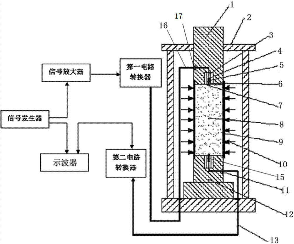
[0046] The dual bending element ultrasonic sensing test device for evaluating rock damage in this embodiment, such as figure 1 As shown, including pressure chamber, rock sample 8 and ultrasonic probe;

[0047] The pressure chamber includes a shell 2, an indenter 1 and a base 12. The base 12 is placed in the shell 2 and is located at the bottom of the shell 2. A part of the indenter 1 enters the shell 2 through the upper opening of the shell 2. The central axis of the base 12 and the indenter The central axis of 1 coincides;

[0048] The rock sample 8 is located between the base 12 and the indenter 1. The rock sample 8 is sealed with a heat-shrinkable tube 9. The heat-shrinkable tube 9 is a rubber tube to prevent hydraulic oil from contacting the rock sample 8. The heat-shrinkable tube The lower end of 9 is fixedly connected to the base ...


PUM


Abstract

The invention discloses a double-bending-element ultrasonic sensing test device for evaluating rock damage. The double-bending-element ultrasonic sensing test device comprises a pressure chamber, a rock sample and an ultrasonic probe, wherein the pressure chamber comprises a housing, a pressure head and a base; the rock sample is positioned between the base and the pressure head; grooves are formed in the sides of the pressure head and the base, in contact with the rock sample; seat cores are arranged in the grooves; the ultrasonic probe comprises an ultrasonic emission probe and an ultrasonic receiving probe; the ultrasonic emission probe and the ultrasonic receiving probe are placed in the pressure head and the seat cores of the base respectively; each ultrasonic probe adopts a double-bending-element structure formed by bonding two bending elements in parallel; and a signal generator, a signal amplifier, an oscilloscope, a first circuit converter and a second circuit converter are arranged outside the pressure chamber. The connection mode of the two bending elements is changed through the circuit converters, the vibration directions of the bending elements are controlled for achieving sequential excitation of longitudinal waves and horizontal waves, the test device is suitable for a rock mechanic ultrasonic test, and the rock damage characteristic is evaluated through wave speed change.

Description

technical field [0001] The invention belongs to the technical field of ultrasonic sensing, in particular to a double bending element ultrasonic sensing test device and method for evaluating rock damage. Background technique [0002] Ultrasonic detection technology is widely used in rock mechanics. Ultrasonic detection has the advantages of convenient operation, no damage, low cost, and large amount of rock information. In the ultrasonic test of rock mechanics, the wave velocity is closely related to the rock mass density, water content, elastic modulus, and uniaxial compressive strength, and the ultrasonic attenuation has a certain relationship with the rock mass damage and internal cracks. Under the current test conditions, the longitudinal wave test is widely used because the probe is easy to manufacture, the signal generation is simple and the signal is easy to identify. The wave velocity ratio between the longitudinal wave and the shear wave can be used to explore the P...

Claims


Application Information

Patent Timeline
Patent Type & Authority Applications(China)
IPC IPC(8): G01N29/04
Inventor 张希巍冯夏庭徐帅孔瑞赵永川
Owner NORTHEASTERN UNIV
Why Eureka
Try Eureka