Supercharge Your Innovation With Domain-Expert AI Agents!

Method for sealing organic light emitting diode by frit

A light-emitting diode and glass frit technology, which is applied in the manufacture of electrical components, electric solid devices, semiconductor/solid-state devices, etc., can solve the problems of the influence of the bonding strength between the cover plate and the substrate, reducing the life of the light-emitting diode, and the large temperature gradient of the glass frit. , to achieve the effect of small implementation difficulty, improve yield and overall quality, and reduce thermal stress

Inactive Publication Date: 2013-01-16
SICHUAN CCO DISPLAY TECH
View PDF7 Cites 19 Cited by
  • Summary
  • Abstract
  • Description
  • Claims
  • Application Information

AI Technical Summary

Problems solved by technology

It is precisely because of these characteristics of laser heating that there are some shortcomings in this packaging method. Laser heating causes the glass frit to heat up and cool down rapidly, the temperature change range is large and the change speed is fast, and the internal temperature gradient of the glass frit is large. During the heating and cooling process Large thermal stress is generated in the glass frit, and cracks are easy to occur in the glass frit, especially at the junction of the glass frit, the cover plate and the substrate, which will not only affect the bonding strength of the cover plate and the substrate, but also greatly reduce the sealing performance. , the water and oxygen in the air will enter the inside of the light-emitting diode through the gap, corrode the internal components, and reduce the life of the light-emitting diode

Method used


Image

  • Method for sealing organic light emitting diode by frit

Examples


Embodiment Construction

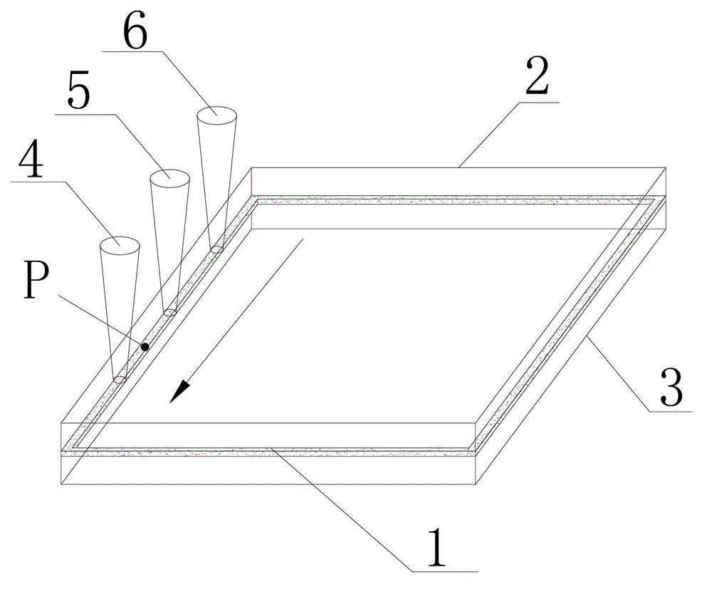
[0012] like figure 1 As shown, the glass frit 1 is arranged between the cover plate 2 and the substrate 3, the first laser beam 4 passes through the cover plate 2, focuses on the glass frit 1, heats the glass frit 1, and the temperature of the glass frit 1 rises instantaneously to reach At the melting point, the glass frit 1 melts to bond the cover plate 2 and the substrate 3 together. The glass frit 1 is cooled and solidified to form a glass wall and play a sealing role. The method for sealing the organic light-emitting diode with glass frit is to divide the heating of the glass frit 1 into three steps, that is, use the first laser beam 4 to preheat the glass frit 1, use the second laser beam 5 to melt the glass frit 1, and use the second laser beam 5 to melt the glass frit 1. The three laser beams 6 delay the cooling speed of the glass frit 1 . Taking point P in the figure as an example, the first laser beam 4 , the second laser beam 5 and the third laser beam 6 move in th...


PUM

PropertyMeasurementUnit
melting pointaaaaaaaaaa

Abstract

The invention provides a method for sealing an organic light emitting diode by frit. The method comprises the following steps: providing a sealing layer between a cover plate and a base plate, wherein the sealing layer is frit arranged to be closed in a circle along the edge of the base plate, and the melting point temperature of the frit is lower than the melting point temperature of the cover plate and the base plate, and the frit is heated to be molten, and then respectively bonded with the cover plate and the base plate; and after the frit is cooled, the frit and the cover plate and the base plate together form an enclosed cavity. The heating process comprises the following steps: irradiating the frit by a first laser beam, so that the temperature of the frit rises to be lower than the melting point temperature thereof; irradiating the frit by a second laser beam, so that the temperature of the frit is higher than the melting point temperature thereof and lower than the melting point temperature of the cover plate and the base plate; and irradiating the frit by a third laser beam, so that the temperature of the frit is lower than the melting point temperature thereof and higher than room temperature. By adopting the method for sealing an organic light emitting diode by frit provided by the invention, the changing speed of the temperature of the frit can be lowered, the heat stress of the frit is reduced, cracks and clearances are avoided, and the bonding strength and sealing effect of the frit are improved.

Description

technical field [0001] The invention relates to a method for sealing an organic light-emitting diode with glass frit. Background technique [0002] At present, glass frit is generally used as a sealing and bonding material when packaging organic light-emitting diodes. After melting, the glass frit is bonded to the substrate and cover plate. After cooling, the glass frit forms a sealing layer and forms a seal with the substrate and cover plate. The cavity, the light-emitting chip is set in the sealed cavity. Moreover, when heating the glass frit, laser heating is used. Since the cover plate is a transparent material, the laser beam passes through the cover plate and focuses on the glass frit. The glass frit contains substances that absorb light, and the light energy is converted into heat energy. The glass frit is heated and melted to play the role of bonding and sealing. The characteristics of laser heating are heat concentration, fast heating speed, instantaneous increase...

Claims


Application Information

Patent Timeline
Patent Type & Authority Applications(China)
IPC IPC(8): H01L51/56H01L51/52
Inventor 唐凡高昕伟李园利
Owner SICHUAN CCO DISPLAY TECH
Features
  • R&D
  • Intellectual Property
  • Life Sciences
  • Materials
  • Tech Scout
  • Unparalleled Data Quality
  • Higher Quality Content
  • 60% Fewer Hallucinations
Learn More