
Structure of rotor of three-phase permanent-magnet synchronous motor

A technology of rotor structure and permanent magnet synchronization, applied in the direction of magnetic circuit shape/style/structure, magnetic circuit rotating parts, etc., can solve the problems of difficult to keep up with the production progress, difficult to form mass production, troublesome processing, etc., to achieve improved Efficiency, cost saving, simple structure effect

Inactive Publication Date: 2013-01-16
WUXI XISHAN SPECIAL FAN
View PDF6 Cites 4 Cited by
  • Summary
  • Abstract
  • Description
  • Claims
  • Application Information

AI Technical Summary

Problems solved by technology

[0004] However, the permanent magnet synchronous motor adopts the rotor straight slot, which also has the following defects: when the straight tile-shaped magnetic steel is placed in the arc-shaped straight slot of the rotor, it is necessary to additionally set up a magnetic isolation gap at both ends of the arc-shaped straight slot in the circumferential direction. Processing is more troublesome, and it is difficult to form mass production
Especially for the large-volume demand of chemical fiber spinning and texturing machines, it is difficult to keep up with the production progress

Method used


Image

  • Structure of rotor of three-phase permanent-magnet synchronous motor
  • Structure of rotor of three-phase permanent-magnet synchronous motor
  • Structure of rotor of three-phase permanent-magnet synchronous motor

Examples


Embodiment Construction

[0024] The specific embodiments of the present invention will be further described below in conjunction with the accompanying drawings.

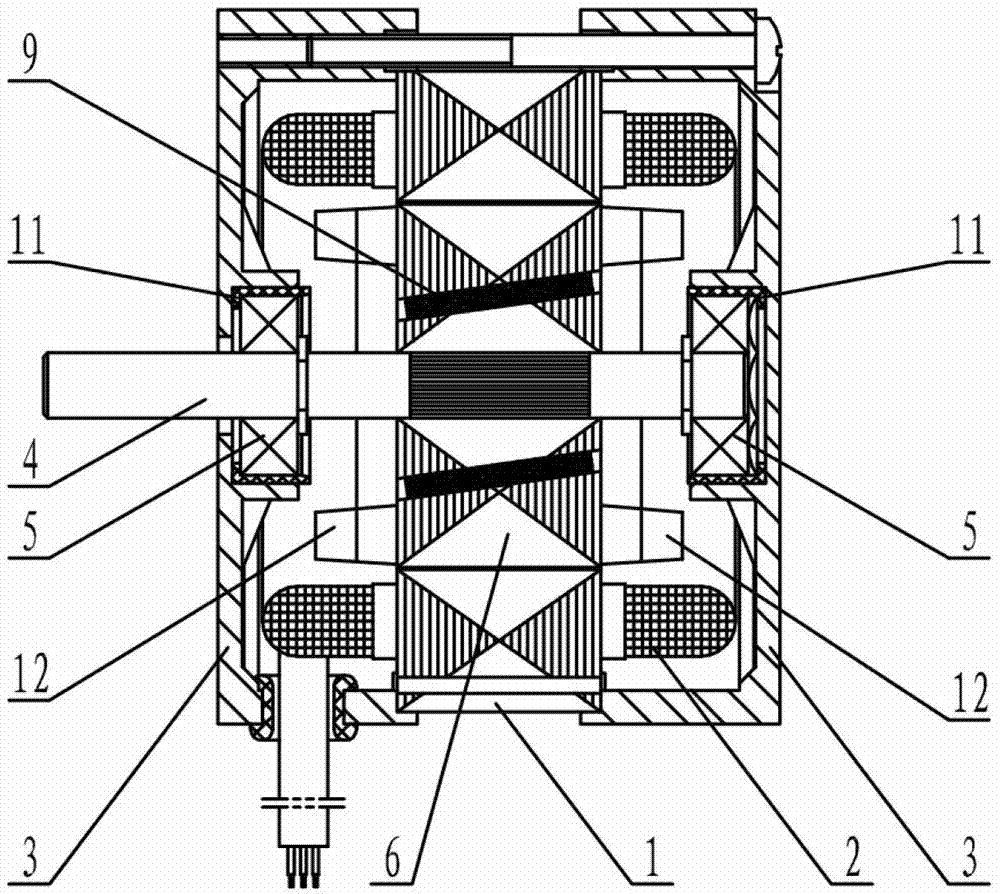
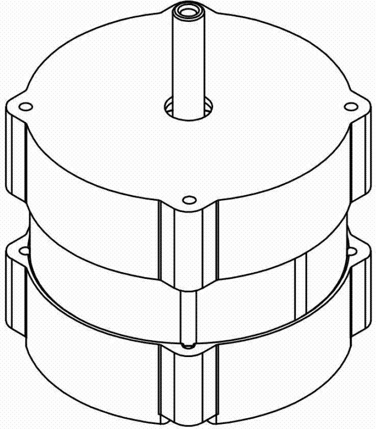
[0025] figure 1 , figure 2 A three-phase permanent magnet synchronous motor adopting the rotor structure of the present invention is shown, which mainly includes a stator core 1 , a coil 2 , an end cover 3 , a rotating shaft 4 and a rotor 6 . Stator core 1 is embedded with coil 2 , both ends are respectively connected with end cover 3 , rotating shaft 4 protrudes from one end of end cover 3 through bearings 5 ​​arranged at both ends, and rotor 6 is connected to rotating shaft 4 .

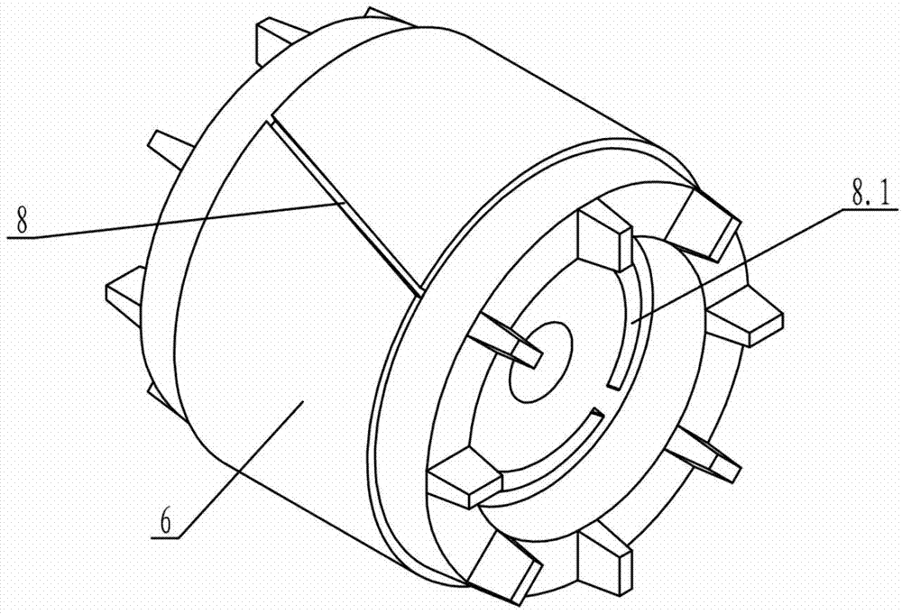
[0026] Such as Figure 3 to Figure 6 As shown, the stator core 1 and the rotor 6 are provided with slot structures that cooperate with each other. The rotor 6 of the present invention is made of silicon steel sheets punched with cast aluminum grooves punched on the outer circumference and arc-shaped magnetic steel grooves punched inside and laminated with cast...


PUM


Abstract

The invention discloses a structure of the rotor of a three-phase permanent-magnet synchronous motor. The rotor is formed by casting aluminium on a silicon steel sheet axially slantwise in an overlaying way, wherein an aluminium casting slot is punched on the outer circumference of the silicon steel sheet, and an arc-shaped magnetic steel slot is punched in the silicon steel sheet; rotor slantwise slots and an arc-shaped slantwise slots are formed on the rotor; the magnetic steel is arranged in each arc-shaped slantwise slot of the rotor; and the magnetic steel is made of the adhesive rare-earth permanent-magnet material and is in the shape of an inclined tile. Because the rotor slantwise slots are adopted, the magnetic vibration and the noise are reduced greatly, the loss is reduced, and the efficiency is improved. When the magnetic steel in the shape of the inclined tile is arranged in the rotor slantwise slots, the fit clearance of the magnetic steel in the circumferential direction isolates magnetism naturally, thus the strength of the punched sheet is improved effectively, and the rotor can be processed conveniently by adopting the mature asynchronous motor rotor aluminum casting process. The three-phase permanent-magnet synchronous motor is simple in structure, can operate stably and reliably, has high efficiency and a wide range of speed regulation and outputs at constant torque. A simple and effective open-loop control system with constant rotation speed requirements can be formed, and the cost spent constructing a control system is saved.

Description

technical field [0001] The invention belongs to the field of motors, and relates to a three-phase permanent magnet synchronous motor, in particular to a rotor structure of an asynchronous start permanent magnet synchronous motor suitable for chemical fiber spinning and texturing machines. Background technique [0002] In recent years, with the rapid development of power electronics technology, microelectronics technology, new motor control theory and rare earth permanent magnet materials, permanent magnet synchronous motors have been rapidly popularized and applied. Permanent magnet synchronous motor is an energy-saving motor with constant speed and strict relationship between speed and power frequency. It is widely used because of its simple structure, reliable operation, small size, low loss and high efficiency. Today, when energy saving and environmental protection are paid more and more attention, it is very necessary to study it. [0003] In view of the fact that the p...

Claims


Application Information

Patent Timeline
Patent Type & Authority Applications(China)
IPC IPC(8): H02K1/27
Inventor 陆志林
Owner WUXI XISHAN SPECIAL FAN
Learn More