Composite bending vibration biped rotating ultrasonic motor vibrator

An ultrasonic motor, bending vibration technology, applied in the direction of generator/motor, piezoelectric effect/electrostrictive or magnetostrictive motor, electrical components, etc. High torque output, easy control, flexible design effect

Active Publication Date: 2016-01-20
HARBIN INST OF TECH
View PDF5 Cites 0 Cited by
  • Summary
  • Abstract
  • Description
  • Claims
  • Application Information

AI Technical Summary

Problems solved by technology

[0004] The purpose of the present invention is to solve the problem of complex application of preload between the driving foot and the rotor existing in the existing "longitudinal-bending composite mode sandwich type biped rotary ultrasonic motor vibrator with elastic support". The present invention provides a A Composite Bending Vibration Biped Rotating Ultrasonic Motor Vibrator

Method used


Image

  • Composite bending vibration biped rotating ultrasonic motor vibrator
  • Composite bending vibration biped rotating ultrasonic motor vibrator
  • Composite bending vibration biped rotating ultrasonic motor vibrator

Examples


specific Embodiment approach 1

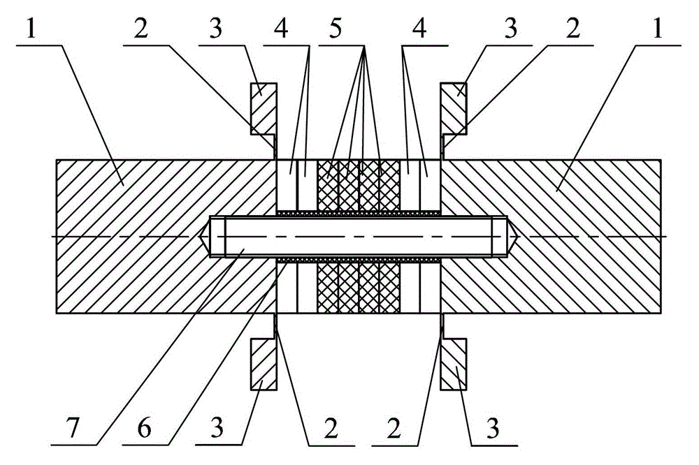
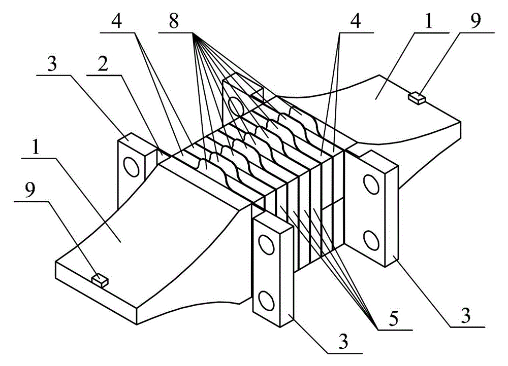
[0019] Specific implementation mode one: the following combination Figure 1 to Figure 3 Describe this embodiment, the composite bending vibration biped rotating ultrasonic motor vibrator described in this embodiment, it includes two end caps 1, four thin-walled beams 2, four mounting seats 3, and four pieces of vertical bending vibration piezoelectric ceramic sheets 4. Four horizontal bending piezoelectric ceramic sheets 5, insulating sleeve 6, studs 7, nine electrode sheets 8 and two friction sheets 9;

[0020] Each of the end caps 1 is a block with a rectangular cross-section and tapering. A blind hole with an internal thread is provided in the center of the large end surface of the end cap 1, and the large end surface of each end cap 1 is symmetrical on both sides. There are two thin-walled beams 2, and each thin-walled beam 2 is provided with a mounting seat 3 on the outside; both ends of the stud 7 are threaded; four vertical bending vibration piezoelectric ceramic sheet...

specific Embodiment approach 2

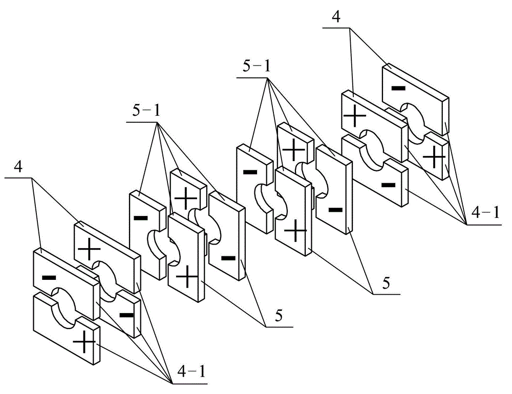
[0025] Embodiment 2: The difference between this embodiment and the composite bending vibration biped rotating ultrasonic motor vibrator described in Embodiment 1 is that the vertical bending vibration piezoelectric ceramic sheet 4 and the horizontal bending vibration piezoelectric ceramic sheet 5 The shape is the same, and their cross-sections are all square or round.

specific Embodiment approach 3

[0026]Embodiment 3: The difference between this embodiment and the composite bending vibration biped rotating ultrasonic motor vibrator described in Embodiment 1 is that the end cover 1, the thin-walled beam 2 and the mounting seat 3 are one piece; the thin-walled beam 2 can The effects of elastic support and vibration isolation can be achieved, and the influence of the connection between the vibrator and other components on the bending vibration mode of the vibrator can be minimized.


PUM


Abstract

A double-leg rotating ultrasonic motor oscillator of combined torsional oscillation relates to the technical field of piezoelectric ultrasonic motors. The problem that preloaded pressure is difficultly applied between driving legs and rotors in the existing sandwich type double-leg rotating ultrasonic motor oscillator of a longitudinal and torsional combined mode is solved. End covers of an oscillator are gradually narrowed blocks of which the cross section is rectangular, two thin-walled beams are symmetrically arranged on the two sides of the big end surfaces of the end covers, a mounting base is arranged on the outer sides of the thin-walled beams, both four vertical torsional oscillation piezoelectric ceramic sheets and four horizontal torsional oscillation piezoelectric ceramic sheets are sheathed on screw bolts, the four horizontal torsional oscillation piezoelectric ceramic sheets are arranged in middle positions, two vertical torsional oscillation piezoelectric ceramic sheets are arranged on the two sides of each horizontal torsional oscillation piezoelectric ceramic sheet, and the two end covers are respectively screwed to the two ends of the screw bolts by threaded holes in the big end surfaces of the end covers so that the vertical torsional oscillation piezoelectric ceramic sheets and the horizontal torsional oscillation piezoelectric ceramic sheets are tightly pressed between the two end covers. The oscillator can be used in the manufacture field of the ultrasonic motors.

Description

technical field [0001] The invention relates to a vibrator of a composite bending-vibration biped rotating ultrasonic motor, which belongs to the technical field of piezoelectric ultrasonic motors. Background technique [0002] Piezoelectric ultrasonic motor is a kind of piezoelectric ultrasonic motor that uses the inverse piezoelectric effect of piezoelectric ceramics to excite vibration in the ultrasonic frequency range in the elastic body, and forms a particle motion with a specific trajectory at a specific point or area on the surface of the elastic body, and then passes through the stator, The frictional coupling between the rotors converts the microscopic motion of the particle into the macroscopic motion of the rotor, which has the advantages of low speed and high torque, no need for a speed change mechanism, no electromagnetic interference, fast response, and self-locking when power is off. [0003] Due to the simplicity of the excitation principle and the simplicity...

Claims


Application Information

Patent Timeline
Patent Type & Authority Patents(China)
IPC IPC(8): H02N2/12
Inventor 刘英想陈维山刘军考石胜君
Owner HARBIN INST OF TECH
Why Eureka
Try Eureka