Eureka AIR delivers breakthrough ideas for toughest innovation challenges, trusted by R&D personnel around the world.

Multi-channel high-speed digital-to-analogue converter (DAC) synchronization method

An implementation method and multi-channel technology, applied in the field of multi-channel high-speed DAC synchronization and phase synchronization control, can solve the problems of no way to synchronize or control the timing, low clock speed, no phase control of the frequency divider, etc., to achieve timing Fully synchronized and controllable, improve work efficiency, and expand the effect of signal output bandwidth

Active Publication Date: 2013-01-16
TSINGHUA UNIV
View PDF2 Cites 20 Cited by
  • Summary
  • Abstract
  • Description
  • Claims
  • Application Information

AI Technical Summary

Problems solved by technology

[0003] Traditional DAC synchronization usually designs multiple low-speed DAC chips on one board, and the data and clock of the DAC are generated by the FPGA, so that there will be no clock crossing, and the timing control of the output of multiple low-speed DACs can be realized, but this The solution can only generate analog signals below 100MHz, and the bandwidth is small, so it cannot adapt to the radar simulation of the modern system
In order to improve the output signal bandwidth, we can only rely on high-speed DAC, but the clock speed of FPGA is not higher than 750MHz at present, so the clock of DAC with speed exceeding 1GHz cannot be directly transmitted to FPGA, so high-speed DAC can only divide the frequency of the clock, such as 1.2 GHz DAC, output a 600MHz reference clock signal to FPGA, FPGA uses this reference clock for timing synchronization
For high-speed DAC, since the clock cannot be provided by FPGA, it can only rely on external analog clock for digital-to-analog conversion. At this time, high-speed DAC needs to use a frequency divider to convert the external high-speed analog clock into a digital clock that FPGA can receive. The frequency divider has no phase control function, so in the digital domain of the FPGA, there is no way to fully synchronize or control the timing, especially for multi-chip FPGA+multi-chip high-speed DAC, this problem is even more serious

Method used


Image

  • Multi-channel high-speed digital-to-analogue converter (DAC) synchronization method
  • Multi-channel high-speed digital-to-analogue converter (DAC) synchronization method
  • Multi-channel high-speed digital-to-analogue converter (DAC) synchronization method

Examples


Embodiment Construction

[0027] Embodiments of the present invention are described in detail below, examples of which are shown in the drawings, wherein the same or similar reference numerals designate the same or similar elements or elements having the same or similar functions throughout. The embodiments described below by referring to the figures are exemplary only for explaining the present invention and should not be construed as limiting the present invention.

[0028] In the description of the present invention, unless otherwise specified and limited, it should be noted that the terms "installation", "connection" and "connection" should be understood in a broad sense, for example, it can be mechanical connection or electrical connection, or two The internal communication of each element may be directly connected or indirectly connected through an intermediary. Those skilled in the art can understand the specific meanings of the above terms according to specific situations.

[0029] The present ...


PUM


Abstract

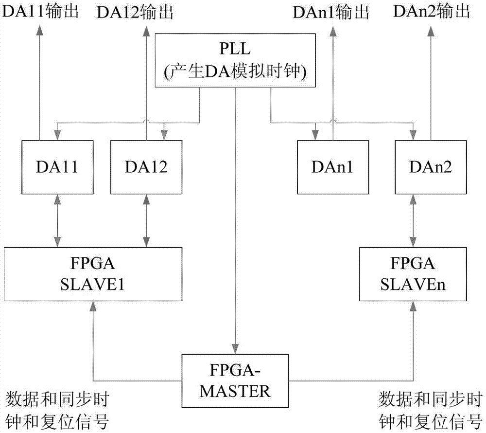
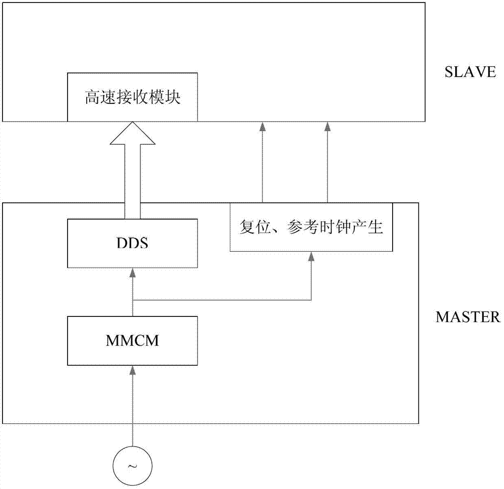
The invention discloses a multi-channel high-speed digital-to-analogue converter (DAC) synchronization method, which comprises the following steps of: first generating a digital signal source reference signal, a synchronous clock signal and a resetting signal by using a field programmable gate array-MASTER (FPGA-MASTER), simultaneously transmitting the signals to an FPGA-SLAVEP and a DACM, and roughly adjusting multi-path delay, wherein P and M are positive integers; then performing FPGA-MASTER synchronous clock phase discrimination in the FPGA-SLAVEP, and regulating a phase difference to 0 by using a fine delay module; and finally performing DACM reference clock phase discrimination in the FPGA-SLAVEP, and regulating a phase difference to 0 by using the fine delay module. Output signals can be subjected to phase synchronization, a plurality of FPGAs and a plurality of high-speed DACs can be simultaneously cascaded without the limitation of clock speed of the DACs, and FPGA-SLAVEPs are used for performing phase discrimination and phase regulation on the FPGA-MASTER and the DACs to make the phases of data of the FPGA-MASTER, the FPGA-SLAVEs and the DACs consistent, so that the time sequence of each path of DAC is completely synchronous and controllable, working efficiency is improved, and a signal output bandwidth is expanded.

Description

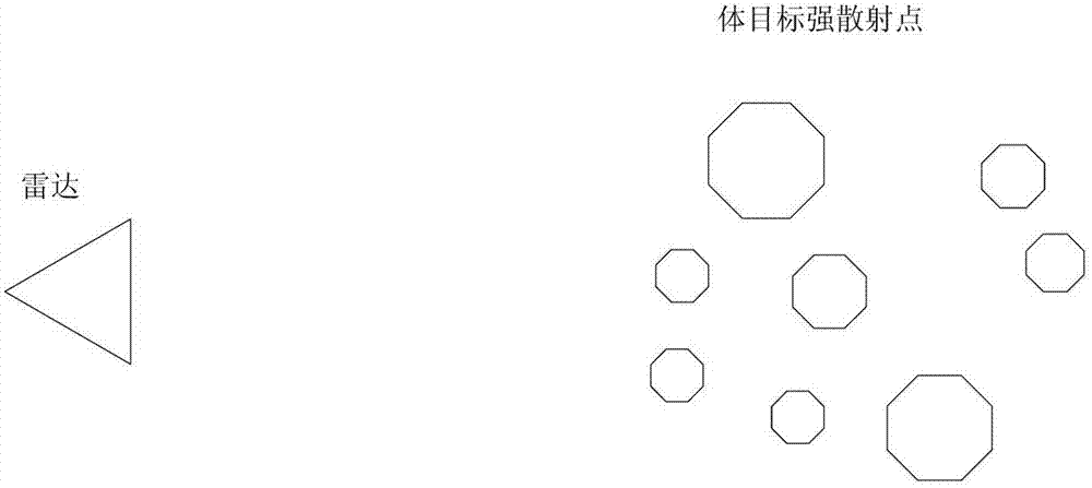
technical field [0001] The invention belongs to the technical field of radar radio frequency simulation, relates to a multi-channel high-speed DAC synchronous realization method, in particular to a method for realizing phase synchronous control of analog output signals through multi-chip FPGAs and multi-chip high-speed DACs. Background technique [0002] For some body target simulations, such as figure 1 As shown, the volume target is composed of multiple strong scattering points, and the amplitude, phase, Doppler and distance of each strong scattering point need to be precisely controlled by software to achieve the simulation results, especially the precise control of the phase, so the simulation begins When , the initial phase difference of each strong scattering point is required to remain fixed, that is to say, the initial phase of each DAC output signal must be consistent. [0003] Traditional DAC synchronization usually designs multiple low-speed DAC chips on one boar...

Claims


Application Information

Patent Timeline
Patent Type & Authority Applications(China)
IPC IPC(8): H04L7/04
Inventor 梁志恒陶青长孙亚光宋兵兵
Owner TSINGHUA UNIV
Why Eureka
Eureka Blog
Learn More