Rapidly-inflatable-deployment thin-film support tube for space craft

An inflatable deployment and support tube technology, which is used in aircrafts, aerospace vehicles, aerospace equipment, etc., can solve the problems of low deployment reliability, long deployment time, and length limitations of mechanical joints, and achieve stable and reliable deployment process. Short time, light weight effect

Active Publication Date: 2013-01-23
HARBIN INST OF TECH
View PDF5 Cites 9 Cited by
  • Summary
  • Abstract
  • Description
  • Claims
  • Application Information

AI Technical Summary

Problems solved by technology

[0003] The purpose of the present invention is to solve the problems that the inflatable and unfolded film support tube of the existing space vehicle is a mechanically unfolded structure, the structure itself is heavy, the reliability of the mechanical joints is low, the length after unfolding is limited, and the unfolding time is long, and provides A film support tube for rapid inflation and deployment of space vehicles

Method used


Image

  • Rapidly-inflatable-deployment thin-film support tube for space craft
  • Rapidly-inflatable-deployment thin-film support tube for space craft
  • Rapidly-inflatable-deployment thin-film support tube for space craft

Examples


specific Embodiment approach 1

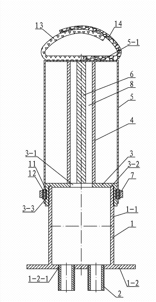
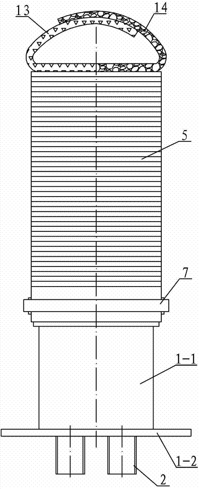
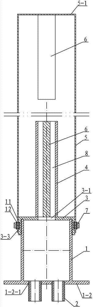
[0009] Specific implementation mode one: combine figure 1 , image 3 and Figure 6 Describe this embodiment, this embodiment includes air collector 1, upper end cover 3, airflow conduit 4, folded film tube 5, direction mark 6, clamp 7, direction mark conduit 8, inner rubber ring 11, outer rubber ring 12, adhesive Clasp 13, Velcro hair 14 and at least three connecting pipes 2, the air accumulator 1 includes a cylinder body 1-1 and a lower end cover 1-2, the lower end cover 1-2 is arranged at the lower end of the cylinder body 1-1, and the cylinder body 1 -1 is integrated with the lower end cover 1-2, the upper end cover 3 is arranged on the upper end of the cylinder 1-1, and the upper end cover 3 is threaded with the cylinder 1-1, and the upper end cover 3 is provided with the cylinder 1 The upper end cover vent hole 3-1 that the inner cavity of -1 communicates, the lower end cover 1-2 is evenly distributed along the same circumference with at least three lower end cover thre...

specific Embodiment approach 2

[0010] Specific implementation mode two: combination Figure 5 To illustrate this embodiment, the cross-sectional shape of the direction mark 6 in this embodiment is in the shape of a "cross", and the cross-sectional shape of the lumen of the direction mark catheter 8 coincides with the "cross" shape of the direction mark 6. The "ten" shape enables the film support tube to run straight after inflated and expanded, and avoids twisting of the film support tube. Other components and connections are the same as those in the first embodiment.

specific Embodiment approach 3

[0011] Specific implementation mode three: combination Figure 6 To illustrate this embodiment, an annular groove 3-2 is provided at a position corresponding to the bottom end surface of the inner cavity of the upper end cover 3 of this embodiment and the upper end surface of the cylinder 1-1. Other compositions and connections are the same as those in Embodiment 1 or 2.


PUM


Abstract

The invention discloses a rapidly-inflatable-deployment thin-film support tube for a space craft, and relates to an inflatable-deployment thin-film support tube for a space craft, for solving the problems of high self-weight, limit on the length after deployment, and long deployment time of the present inflatable-deployment thin-film support tube for a space craft due to a mechanical deployment structure. According to the invention, an upper end cover is arranged at the upper end of a barrel body and in threaded connection with the barrel body; an airflow guide tube is vertically arranged at the centre of the upper end surface of the upper end cover; the inner cavity of the airflow guide tube is connected with an air vent; one end of a folding thin-film tube is sleeved on the upper end cover; one end of the folding thin-film tube is fastened with the upper end cover via a hoop, and the other end of the folding thin-film tube is a closed-type top; a direction indicator is vertically arranged on the inner wall of the closed-type top; the section shape of the direction indicator is fitted with the section shape of the inner cavity of a direction indicator guide tube; at least three connection tubes are arranged on the outer end surface of a flange; and each lower thread hole is in threaded connection with one connection tube. The rapidly-inflatable-deployment thin-film support tube disclosed by the invention is used for supporting various micro cameras and various magnetometers on satellite detectors and lunar detectors.

Description

technical field [0001] The invention relates to an inflatable and expanded film support tube for a space vehicle, in particular to a film support tube for a space vehicle to quickly inflate and expand. Background technique [0002] The inflatable expansion film support tube for space vehicles is mainly used in satellites and lunar probes. Its function is to support a payload through the inflation and expansion of the inflatable expansion tube, such as supporting a camera or a magnetic needle. The existing technology mainly adopts mechanical unfolding structure, the weight of the structure itself is relatively large, the reliability of mechanical joint unfolding is low, the length after unfolding is limited, and the unfolding time is long. Contents of the invention [0003] The purpose of the present invention is to solve the problems that the inflatable and unfolded film support tube of the existing space vehicle is a mechanically unfolded structure, the structure itself i...

Claims


Application Information

Patent Timeline
Patent Type & Authority Applications(China)
IPC IPC(8): B64G1/66
Inventor 谭惠丰李云良卫剑征赵树林林国昌王长国
Owner HARBIN INST OF TECH
Why Eureka
Try Eureka