Stander of high-speed data transmission system between rotary body and fixed body

A high-speed data transmission, fixed body technology, applied in the direction of machine/support, supporting machine, mechanical equipment, etc., can solve the problem of not meeting the requirements of the data transmission system, and achieve the effect of simple structure, high efficiency, and easy modification

Active Publication Date: 2013-01-23
BEIJING HANGXING MACHINERY MFG CO LTD
View PDF8 Cites 3 Cited by
  • Summary
  • Abstract
  • Description
  • Claims
  • Application Information

AI Technical Summary

Problems solved by technology

However, the frame structure applicable to the carbon brush slip ring mode and the wireless capacitive coupling mode can no longer meet the requirements of the data transmission system proposed in the publication number CN101716082A

Method used


Image

  • Stander of high-speed data transmission system between rotary body and fixed body
  • Stander of high-speed data transmission system between rotary body and fixed body
  • Stander of high-speed data transmission system between rotary body and fixed body

Examples


Embodiment Construction

[0016] The present invention will be further described below with reference to the specific drawings and embodiments.

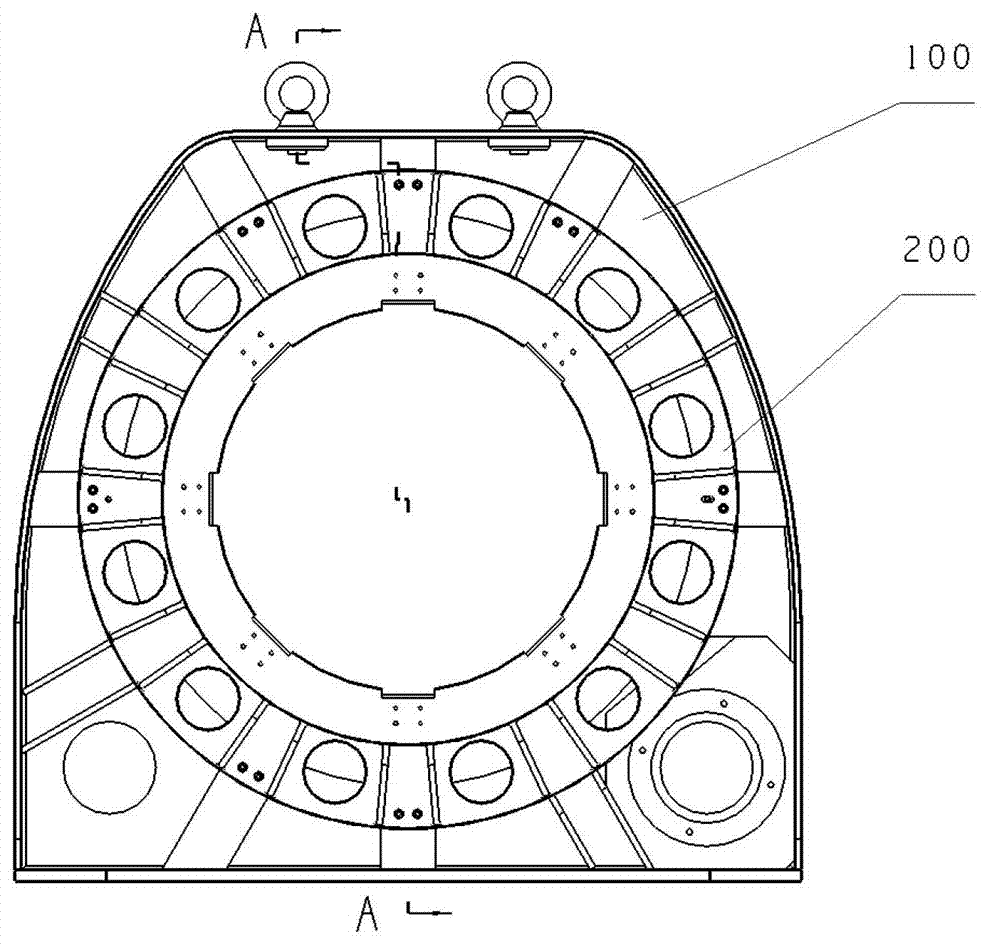
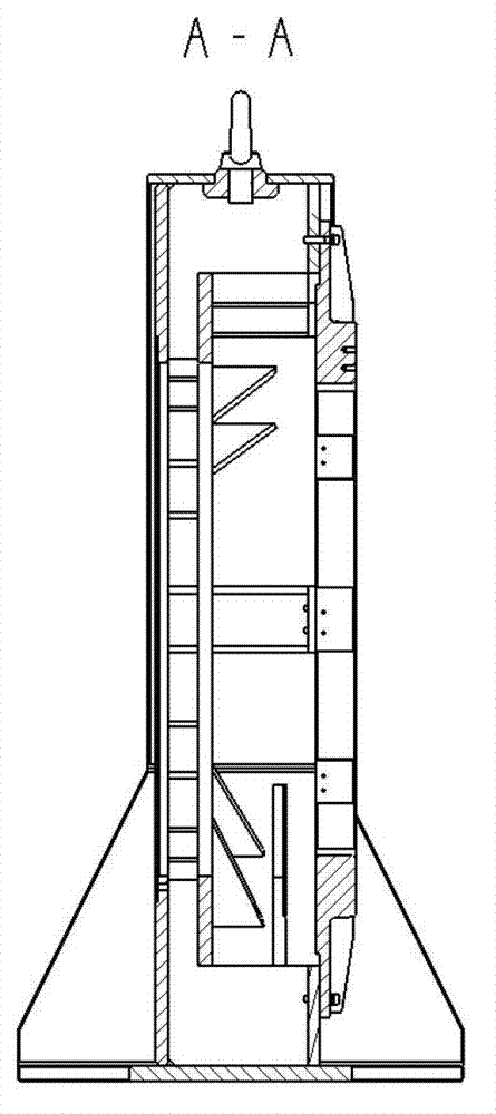
[0017] like figure 1 , 2 As shown, the rack in this embodiment is mainly composed of rack assembly 100 and receiving device mounting part 200 .

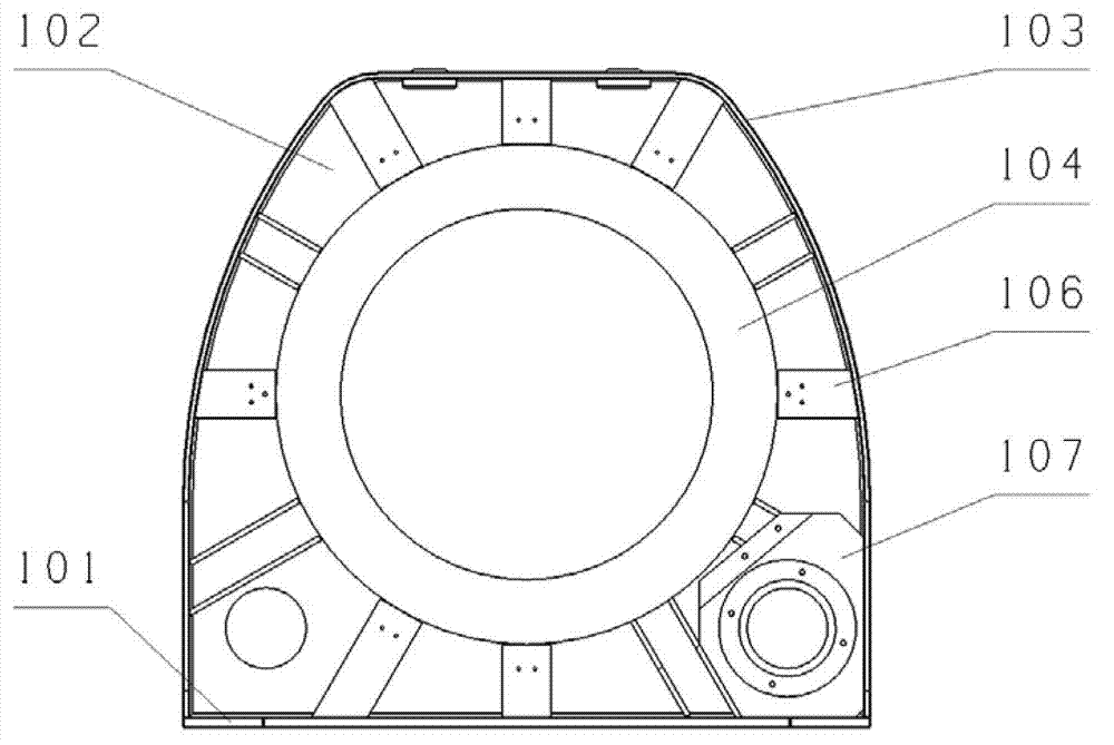
[0018] like Figures 3 to 6 As shown, the rack assembly 100 in this embodiment includes: a bottom plate 101, a vertical plate 102, an inverted U-shaped frame 103, a circular ring plate 104, a trapezoidal plate 105, a plurality of receiving device mounting plates 106, a motor mounting plate 107, a plurality of Each rib 108, etc., are fixedly connected between them. The bottom plate 101 is in the shape of an I-shape, and is laid flat on the bottom of the whole rack welding assembly 100; there is a through hole in the center of the vertical plate 102, the bottom of the vertical plate 102 is vertically fixed on the bottom plate 101, and the upper part of the vertical plate 102 has the same shape as the inverted U-sha...


PUM


Abstract

The invention relates to a stander of a high-speed data transmission system between a rotary body and a fixed body. The stander mainly comprises a stander welding assembly and a receiving device mounting part, which are connected into a whole by a positioning pin and a bolt, wherein the stander welding assembly consists of a base plate, a vertical plate, an inverted U-shaped border, a circular plate, a trapezoid plate, a motor mounting plate and a ribbed plate. The stander is simple and compact in structure, replaces the conventional stander structure applicable to a carbon brush sliding ring mode and a wireless capacitor coupling mode, and can work reliably and meet a use requirement.

Description

technical field [0001] The invention relates to a frame structure suitable for a high-speed data transmission system between a rotating body and a fixed body, in particular to a frame structure suitable for a high-speed data transmission system between a rotating body and a fixed body in a security inspection CT system. Background technique [0002] In the field of industrial technology, there are many applications that need to transmit the data information on the rotating body to the fixed body. Typical applications are in the security inspection CT system. The detected information is transmitted to the stationary body at high speed and reliably. As the security inspection CT system with multi-row X-ray detectors has been widely used in actual inspection, the inspection data collected by the system in a unit time has greatly increased, and the industry has adopted the wireless capacitive coupling method to replace the above carbon brush slip ring However, the electromagnet...

Claims


Application Information

Patent Timeline
Patent Type & Authority Applications(China)
IPC IPC(8): F16M11/00
Inventor 王俊锋王稷徐圆飞温子宽田子夜刘念肖军
Owner BEIJING HANGXING MACHINERY MFG CO LTD
Why Eureka
Try Eureka