
Method and system for reducing consumption in capturing process of CO2 through chemical absorption

A chemical absorption and process technology, applied in chemical instruments and methods, separation methods, and chemical separation, etc., can solve problems such as reduction of output power, impact of steam turbine operation, reduction of power generation efficiency of power plants, etc. Effect of Boiler Heat Load

Active Publication Date: 2013-01-30
NORTH CHINA ELECTRIC POWER UNIV (BAODING)
View PDF6 Cites 17 Cited by
  • Summary
  • Abstract
  • Description
  • Claims
  • Application Information

AI Technical Summary

Problems solved by technology

However, due to the CO in the exhaust 2 The concentration is usually lower than 9%, which is suitable for low concentration CO 2 The separated chemical absorption process needs to consume a lot of medium and low temperature saturated steam for absorbent regeneration. This part of steam is usually taken from steam turbine extraction, resulting in a large reduction in the effective output of the steam cycle (about 20%), which will reduce the power generation efficiency of the power plant. 10-15 percentage points lower, and it will also have a serious impact on the normal operation of the steam turbine, which will cause a series of engineering technical problems
[0004] Obviously, the high energy consumption of the separation system not only greatly reduces the power generation efficiency of coal-fired power plants, but also means an additional increase in energy consumption and CO per unit of power generation. 2 emissions, a price that is unacceptable to the energy system
In other words, from a technical point of view, CO 2 Separation and recovery are relatively mature, but the realization of energy system CO 2 The difficulty of separation lies in how to reduce the decline in power generation system efficiency caused by the separation process by reducing system energy consumption

Method used


Image

  • Method and system for reducing consumption in capturing process of CO2 through chemical absorption
  • Method and system for reducing consumption in capturing process of CO2 through chemical absorption

Examples


Embodiment

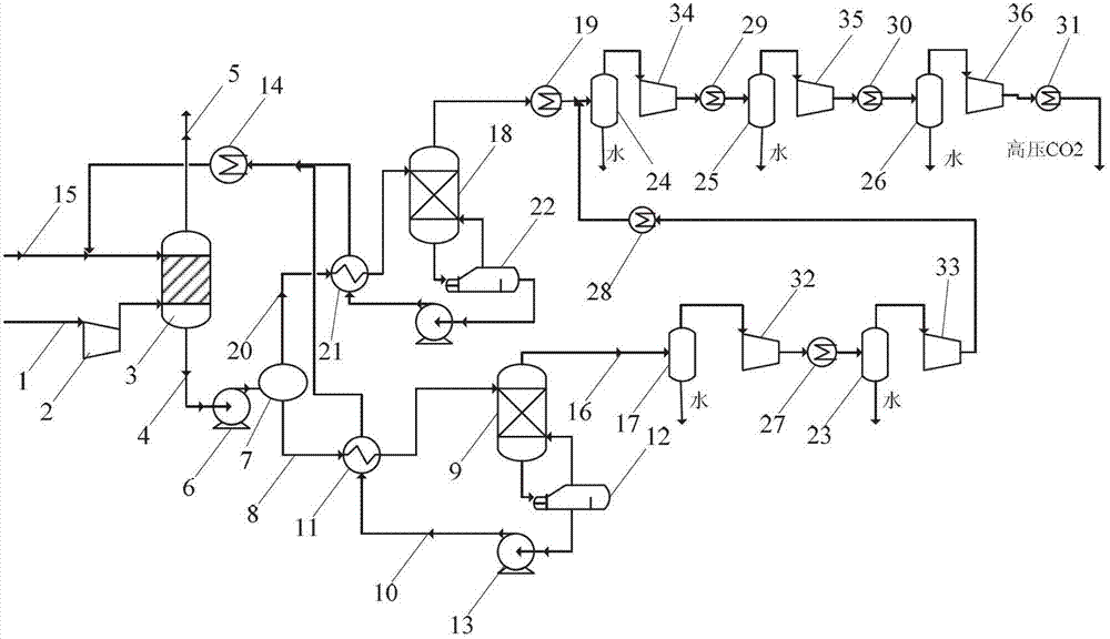
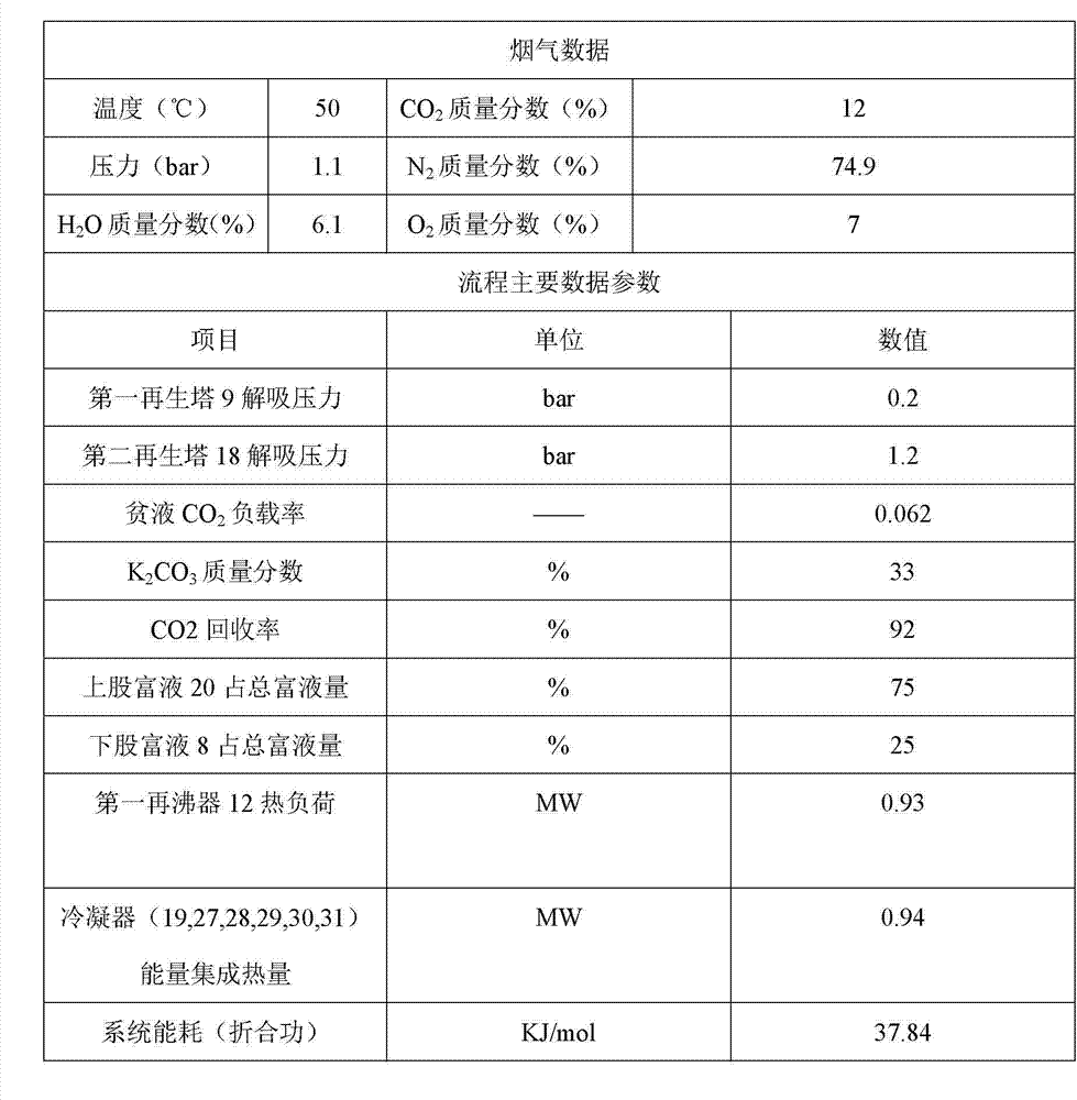
[0023] In this example, the absorbent is K with a mass fraction of 33% 2 CO 3 solution, the number of plates in the absorption tower 3 is 8, the number of plates in the first regeneration tower 9 and the second regeneration tower 18 is 12, CO 2 The lean solution loading α=0.062. System structure such as figure 1 shown

[0024] When working, the flue gas 1 enters the absorption tower 3 after being pressurized by the compressor 2 and is connected with K from top to bottom. 2 CO 3 The solution fully contacts the reaction, K 2 CO 3 The solution fully absorbs CO 2 After becoming the rich liquid 4, it flows out from the bottom of the absorption tower 3, and absorbs the CO 2 The flue gas discharged from the top of the tower becomes exhaust smoke 5.

[0025] After the rich liquid 4 is pressurized by the rich liquid pump 6, the rich liquid 4 is divided into two streams by the separator 7, the circulating flow of the upper rich liquid 20 accounts for 75%, and the lower rich li...


PUM


Abstract

The invention relates to a method and a system for reducing consumption in a capturing process of CO2 through chemical absorption, belongs to the fields of energy utilization, energy conservation and environmental protection. Based on the common CO2 capturing process, the method comprises the following steps that: an absorbent in an absorption tower is used for absorbing CO2 in flue gas and forming a pregnant solution, the obtained pregnant solution is divided into two branches, the two branches of pregnant solution is subjected to CO2 separation in two regeneration towers with different pressures, and waste heat generated during a high-pressure desorption process of the pregnant solution is taken as a heat source of a low-pressure desorption process; CO2 air flows mixed with water vapor after treatment by the regeneration towers are treated by multiple stages of gas-liquid separators, condensers and compressors, so that high-pressure liquid-station CO2 is obtained. With the adoption of the method and the system provided by the invention, the heat consumption during the whole desorption process is reduced, so that the efficient desorption of the pregnant solution flows is realized; under the premise that the capturing rate is 92%, the regenerated energy consumption of an optimal system obtained after improvement of the process is 37.84KJ (reduced work) / mol, and is reduced by 19.77% compared with the energy consumption of 47.16KJ (reduced work) / mol before improvement, and therefore, a new method is provided for reducing the energy consumption for capturing the CO2 with the low energy consumption in thermal power plants.

Description

technical field [0001] The invention belongs to the field of energy utilization, energy saving and environmental protection, and relates to a chemical absorption CO 2 A consumption reduction method and system for a capture process. Background technique [0002] At present, the atmospheric greenhouse effect is one of the biggest environmental problems facing the world. The greenhouse effect caused by greenhouse gas emissions will lead to a series of serious problems such as increased pests and diseases, rising sea levels, abnormal climate, increased ocean storms, land drought, and increased desertification. as a result of. CO in fossil energy systems 2 The large amount of emissions is considered to be the main cause of global warming and the intensification of the greenhouse effect. my country's power industry (mainly a large number of coal-fired power plants) CO 2 Emissions account for about the country's CO 2 About 50% of the total emissions. my country has joined the...

Claims


Application Information

Patent Timeline
Patent Type & Authority Applications(China)
IPC IPC(8): B01D53/78B01D53/62B01D53/96
CPCY02C10/04Y02A50/20Y02C20/40
Inventor 张国强杨勇平翟代龙徐钢杨志平张锴
Owner NORTH CHINA ELECTRIC POWER UNIV (BAODING)
Learn More