

Carrying device and production and reproduction method thereof
A technology of a carrying device and a copying method, which is applied in semiconductor/solid-state device manufacturing, packaging, transportation and packaging, etc., can solve the problems of high production cost and long pallet replacement time.
- Summary
- Abstract
- Description
- Claims
- Application Information
AI Technical Summary
Problems solved by technology
Method used
Image

Examples
no. 1 example
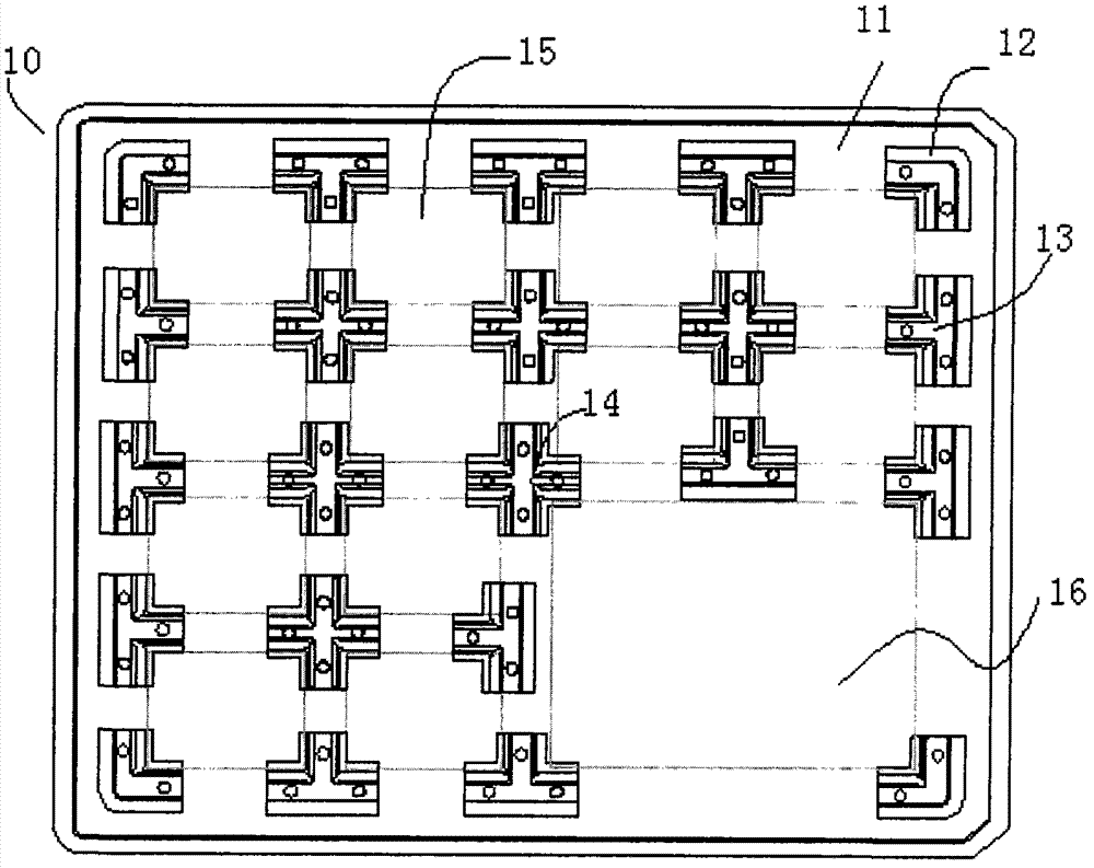
[0053] Such as figure 2 As shown, the carrying device 10 of the first embodiment of the present invention includes a base plate 11 and a plurality of positioning blocks of the same or different shapes, such as an L-shaped positioning block 12 , a T-shaped positioning block 13 and a cross-shaped positioning block 14 . They are assembled on the base plate 11 in different alignment relationships to form a plurality of carrying spaces 15 and carrying spaces 16 of different sizes from the carrying spaces 15 for carrying objects of the same or different sizes, such as touch panels, display panel etc. Wherein, the material of the substrate 11 may be foamed polypropylene or foamed ethylene copolymer.
[0054] Figure 5A It is a structural schematic diagram of the L-shaped positioning block in the carrying device of the present invention, Figure 5B It is the right side view of the L-shaped positioning block. Such as Figure 5A As shown, the L-shaped positioning block 12 includes...
no. 2 example
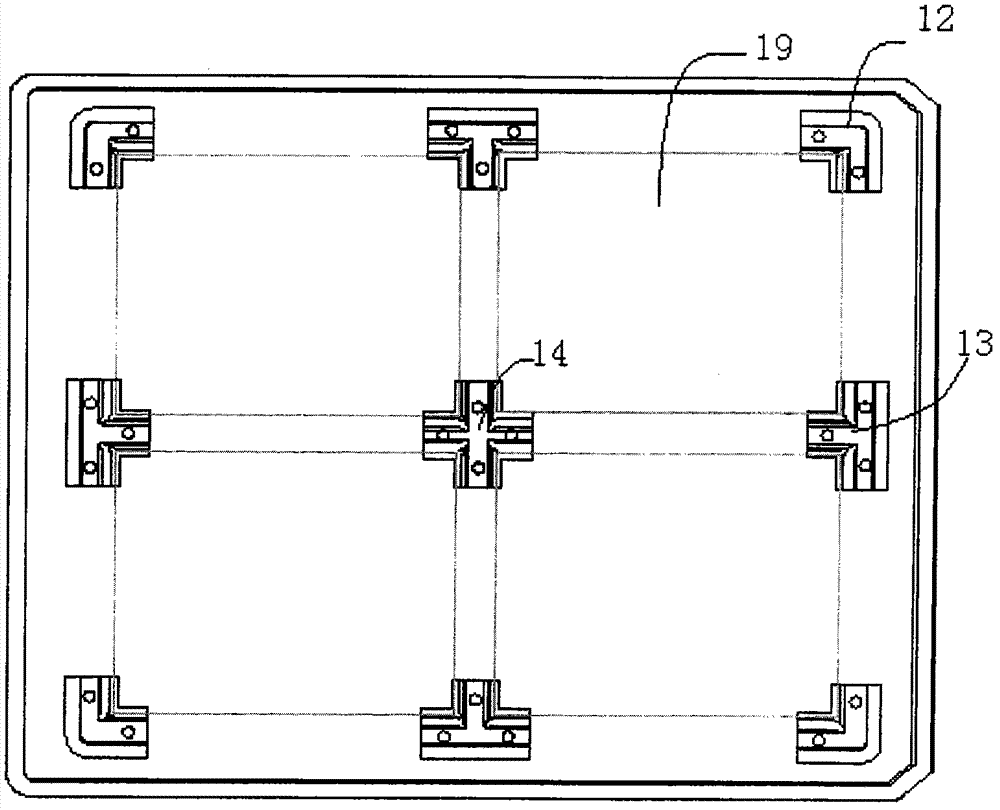
[0062] Figure 4 It is a structural schematic diagram of the second embodiment of the carrying device of the present invention. The carrying device 20 includes a base plate 11 and a cross-shaped positioning block 14 , and the cross-shaped positioning block 14 forms four carrying spaces with the side walls 111 of the base plate 11 .
[0063] Such as Figure 4 As shown, the carrying space formed by the cross-shaped positioning block 14 and the base plate 11 is used to carry four objects to be loaded 41, 42, 43, 44, wherein the base plate 11 includes a side wall 111 and a relief corner 112. The function of the relief corner 112 is that, when carrying an object with a right angle, each right-angled side of the object can abut against the side wall 111 . Correspondingly, the cross-shaped positioning block 14 is fixed on the upper left of the base plate 11 for positioning the four corners of the objects 41 , 42 , 43 , 44 to be loaded with different sizes. Here, the object to be l...
PUM
 Abstract
Description
Claims
Application Information