Desolventizing humidifier

A technology of solvent humidifier and humidifier, which is applied in the direction of fat generation, fat oil/fat production, fat oil/fat refining, etc. It can solve the problems of unsatisfactory recovery effect, long recovery time, long residence time, etc., and shorten the solvent recovery time , The solvent recovery rate is improved, and the effect of improving the recovery utilization rate

Active Publication Date: 2013-01-30
济南中棉生物科技有限公司 +1
View PDF3 Cites 4 Cited by
  • Summary
  • Abstract
  • Description
  • Claims
  • Application Information

AI Technical Summary

Problems solved by technology

[0002] At present, in the cottonseed protein production line, after the dephenolized material is dried by a disc dryer, a part of the solvent still remains in the material, which cannot be completely recovered
One of the existing technologies is to use a disc dryer to recycle the residual solvent, but the disc dryer indirectly heats the material and uses a small amount of direct steam to evaporate the material. Since the steam and the material cannot Complete contact, the recovery effect is not ideal, resulting in high solvent consumption, which affects the economic benefits of the enterprise
[0003] In the prior art, there is also a method of secondary recovery of the residual solvent through the evaporation machine. The evaporation machine uses a large amount of steam to evaporate the solvent in the high material layer, but due to the thick material layer, the material in the equipment If the residence time is long, the color of the material will become darker, the protein will be denatured, and the quality of the product will decrease.
[0004] In summary, the existing secondary desolventization equipment has problems such as low solvent recovery rate, long recovery time, denaturation of cottonseed protein after dephenolization, etc.

Method used


Image

  • Desolventizing humidifier

Examples


Embodiment Construction

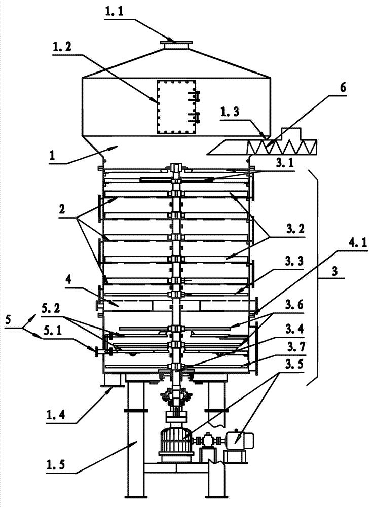
[0022] The specific implementation of the desolventizing humidifier of the present invention will be described in detail below in conjunction with the accompanying drawings.

[0023] as attached figure 1 A kind of precipitation humidifier shown, comprises tank body 1, the multi-layer sieve plate 2 that is fixed in the tank body 1, is fixed on the tank body 1 and is arranged on the steam plywood box I4 of multi-layer sieve plate 2 bottom, sets The blanking device 3 in the tank body 1, the tank body 1 includes an air outlet 1.1 at the top, a feed port 1.3 connected to the feed device 6 and a discharge port 1.4 at the bottom of the tank body 1, The blanking device 3 includes a vertical shaft 3.4 located at the center of the tank body 1 and a drive mechanism 3.5 for driving the rotation of the vertical shaft 3.4, and the vertical shaft 3.4 is fixedly provided with a distributing device 3.1, and The scraper 3.2 on the top of each sieve plate 2 and matched thereto, the inverted pus...


PUM


Abstract

The invention provides a desolventizing humidifier which comprises a tank body, multi-layer sieve plates, a steam plywood case I and a discharge device. The multi-layer sieve plates are fixed in the tank body, the steam plywood case I is fixed on the tank body and arranged at the bottoms of the multi-layer sieve plates, and the discharge device is arranged in the tank body. The tank body comprises a steam outlet, a feed port and a discharge port, wherein the steam outlet is arranged at the top, the feed port is connected with a feed device, and the discharge port is arranged at the bottom of the tank body. The discharge device comprises a vertical shaft arranged in the center of the tank body and a drive mechanism driving the vertical shaft to rotate. A distribution device, scraper boards, a harrow rod I and a harrow rod III are fixed successively on the vertical shaft from top to bottom. The scraper boards are arranged above and matched with the multi-layer sieve plates, the harrow rod I is introversive and arranged above and matched with the steam plywood case I, and the harrow rod III is extroversive and arranged above and matched with the tank body bottom. Steam is fed into the steam plywood case I, and steam outlets are arranged on the upper portion of the steam plywood case I. Compared with the prior art, the desolventizing humidifier has the advantages of being high in solvent recovery rate and dephenolized cottonseed protein quality.

Description

technical field [0001] The invention relates to the field of mechanical equipment, in particular to a dephenolized cottonseed protein processing equipment, specifically a desolventizing humidifier. Background technique [0002] At present, in the cottonseed protein production line, after the dephenolized material is dried by a disc dryer, a part of the solvent still remains in the material, which cannot be completely recovered. One of the existing technologies is to use a disc dryer to recycle the residual solvent, but the disc dryer indirectly heats the material and uses a small amount of direct steam to evaporate the material. Since the steam and the material cannot Complete contact, the recovery effect is not ideal, resulting in high solvent consumption, which affects the economic benefits of the enterprise. [0003] In the prior art, there is also a method of secondary recovery of the residual solvent through the evaporation machine. The evaporation machine uses a large...

Claims


Application Information

Patent Timeline
Patent Type & Authority Applications(China)
IPC IPC(8): C11B1/10C11B3/14
Inventor 刘亚伦张友富牟永世王寿震
Owner 济南中棉生物科技有限公司
Why Eureka
Try Eureka