Valve forming mould covered with wear-resistant heat insulation film layer and manufacturing method of valve forming mould
What is AI technical title?
AI technical title is built by PatSnap AI team. It summarizes the technical point description of the patent document.
A technology for forming molds and heat insulation films, which is applied in the direction of plating, coating, sputtering plating, etc. of superimposed layers. long life effect
Inactive Publication Date: 2013-02-06
HUBEI UNIV OF TECH
View PDF3 Cites 2 Cited by
Summary
Abstract
Description
Claims
Application Information
AI Technical Summary
This helps you quickly interpret patents by identifying the three key elements:
Problems solved by technology
Method used
Benefits of technology
Problems solved by technology
During the forming process, the temperature distribution of the die is extremely uneven. Due to the long contact time between the rounded part and the workpiece, this part and the surrounding area have been at a relatively high temperature, up to 700 ° C, and the temperature changes periodically during the forming process. Creates thermal fatigue, which reduces the strength of the mold, making fillets more prone to damage
Method used
Image
Click on the blue label to locate the original text in one second.
Reading with bidirectional positioning of images and text.
Examples
preparation example Construction
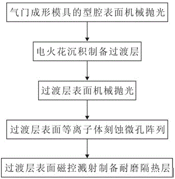
[0026] see figure 1 , the embodiment of the preparation method of the valve forming mold covered with wear-resistant and heat-insulating film layer of the present invention comprises the following steps:
[0027] ①. Mechanically polish the cavity surface of the valve forming mold covered with wear-resistant and heat-insulating film;
[0028] ②. The transition layer is prepared by EDM;
[0029] ③, the surface of the transition layer is mechanically polished;
[0030] ④, Plasmaetching microhole array on the surface of the transition layer;
[0031] ⑤. The wear-resistant and heat-insulating layer is prepared by magnetron sputtering on the surface of the transition layer.
Embodiment 1
[0033] Mold cavity material: 3Cr2W8V.
[0034] Electrospark deposition preparation transition layer (NiCoCrAlY) process parameters: output voltage 100 V, capacitance 150 μF, frequency 2500 Hz, specific deposition time 1.0 min / cm 2 , The electrode speed is 2500r / min.
[0035] The process parameters of plasmaetching microhole array: the degree of vacuum is 1.0Pa, the substrate negative bias is 650V, and the time is 10min.
[0036] Magnetron sputtering to prepare wear-resistant heat insulation layer (ZrO2) process parameters: working pressure 0.1 Pa, loading negative biasvoltage -100 V, sputtering voltage 500 V, target sputtering current density 0.1 A / cm 2 , and the sputtering time was 0.5 hours.
Embodiment 2
[0038] Mold cavity material: 4Cr5MoSiV1.
[0039] Electrospark deposition preparation transition layer (NiCoCrAlY) process parameters: output voltage 150V, capacitance 100μF, frequency 3000Hz, specific deposition time 1.2min / cm 2 , The electrode speed is 3000r / min.
[0040] The process parameters of plasma etching microhole array: the degree of vacuum is 1.2Pa, the substrate negative bias is 700V, and the time is 15min.
[0041] Magnetron sputtering preparation of wear-resistant heat insulation layer (ZrO2) process parameters: working pressure 0.1 Pa, sample loading negative bias -300 V, sputtering voltage 600 V, target sputtering current density 0.12 A / cm2, sputtering time for 1 hour.
PUM
Abstract
The invention provides a manufacturing method of a valve forming mould covered with a wear-resistant heat insulation film layer. The wear-resistant heat insulation film layer covers the surface of a cavity of the valve forming mould and comprises a transition layer and a wear-resistant heat insulation layer; and the transition layer is positioned between the cavity of the valve forming mould and the wear-resistant heat insulation layer. The manufacturing method comprises the steps as follows: (1), mechanically polishing the surface of the cavity of the valve forming mould covered with the wear-resistant heat insulation film layer; (2), preparing the transition layer by using electric spark deposition; (3), mechanically polishing the surface of the transition layer; (4), conducting plasmaetching on the surface of the transition layer to prepare a micropore array; and (5), conducting magnetron sputtering on the surface of the transition layer to prepare the wear-resistant heat insulation layer. The manufacturing method of the valve forming mould covered with a wear-resistant heat insulation film layer can make a guide for production of the valve forming mould covered with the wear-resistant heat insulation film layer.
Description
technical field [0001] The invention relates to a mechanical forming die, in particular to an air valve forming die covered with a wear-resistant and heat-insulating film layer and a preparation method thereof. Background technique [0002] The valve of the engine is an important part of the engine. At present, the final forging after electric upsetting and the final forging after extrusion are mainly used in China to produce blanks. The final forging is one of the key processes in the processing of valve blanks. The final forging of valve blanks During the forming process, due to the violent flow of metal and the harsh working environment of the mold, the life of the mold is very low. Generally, a set of molds can only produce 500-1000 valves. Too low mold life not only significantly increases production costs, but also has a great impact on production efficiency. [0003] During the final forging process of the valve, the metal at the rounded corner always flows to the st...
Claims
Application Information
Patent Timeline
Application Date:The date an application was filed.
Publication Date:The date a patent or application was officially published.
First Publication Date:The earliest publication date of a patent with the same application number.
Issue Date:Publication date of the patent grant document.
PCT Entry Date:The Entry date of PCT National Phase.
Estimated Expiry Date:The statutory expiry date of a patent right according to the Patent Law, and it is the longest term of protection that the patent right can achieve without the termination of the patent right due to other reasons(Term extension factor has been taken into account ).
Invalid Date:Actual expiry date is based on effective date or publication date of legal transaction data of invalid patent.

