Fervent material output machine

A technology for output machines and materials, applied in conveyors, transportation and packaging, lighting and heating equipment, etc., can solve problems such as low reliability, increased wear, automatic tensioning structure of conveying steel belts, etc., to achieve accurate transmission and reliable operation , Save the effect of automatic tensioning device

Active Publication Date: 2013-02-06
陈春梅
View PDF5 Cites 4 Cited by
  • Summary
  • Abstract
  • Description
  • Claims
  • Application Information

AI Technical Summary

Problems solved by technology

[0003] The invention provides a red-hot material output machine, which can solve the problem that the conveying steel belt must be automatically tensioned in the existing dry slag machine, and the resulting complex structure, increased wear, and excessive elongation of the steel belt, as well as the problem of conveying The steel belt cannot withstand the impact of large focal blocks, short life, low reliability and other problems

Method used


Image

  • Fervent material output machine
  • Fervent material output machine
  • Fervent material output machine

Examples


Embodiment Construction

[0038] The present invention will be described in detail below in conjunction with the accompanying drawings and embodiments.

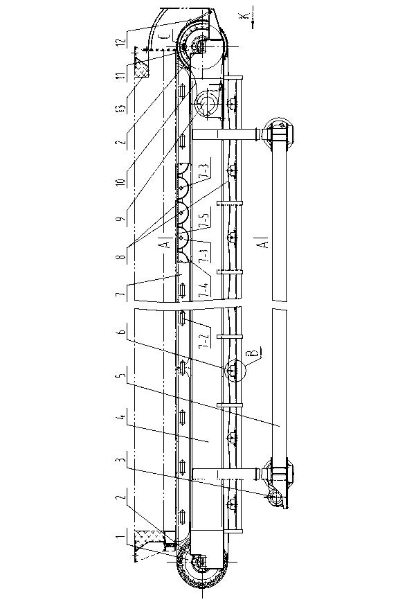
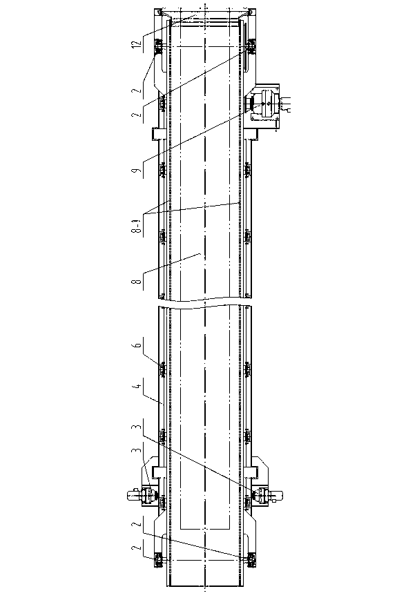
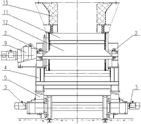
[0039] see figure 1 , figure 2 and Figure 11 , in order to solve the problem that the conveying steel belt in the prior art must be tensioned by an automatic tensioning device with a complex structure and the conveying steel belt cannot bear the impact of a large coke block, etc., a corresponding invention design has been carried out.

[0040] The design concept of the present invention is to include a body 4, a shaft seat 2, a cylindrical driving shaft 11, a cylindrical passive shaft 1, a heat-resistant conveying steel belt 8, a steel belt driving machine 9, a water-filled bed 7 and a plurality of Roller 6. A pair of shaft seats 2 are arranged at both ends of the body 4, and the shaft seats 2 are adjustable shaft seats. A cylindrical driving shaft 11 is installed on a pair of shaft seats 2 at one end, a cylindrical driven shaft 1 is installed o...


PUM


Abstract

The invention provides a fervent material output machine and solves the problem that for a present conveyor, a conveying steel strip has a complex structure and can not bear impact from large coke blocks, which is caused by the fact that the conveying steel strip needs to be tensioned automatically. The technical scheme is adopted as follows: a heat-resisting conveying steel strip is wound between a cylindrical drive shaft and a cylindrical driven shaft; the upper part of the heat-resisting conveying steel strip is a working face which is supported by a water-filled pad bed; the lower part is the return stroke of the heat-resisting conveying steel strip and supported by a plurality of carrier rollers; the water-filled pad bed is welded at the upper part of a machine body, and the plurality of carrier rollers are mounted at the lower part of the machine body; two gears are mounted at the two ends of the cylindrical drive shaft respectively; the two gears at the two ends are both provided with angle adjusters; a row of sprocket holes are formed on each of the two sides of the heat-resisting conveying steel strip; and the sprocket holes on the two sides are meshed with the gears at the two ends of the drive shaft. By adoption of such a transmission manner that the gears of the drive shaft are meshed with the sprocket holes of the heat-resisting conveying steel strip, an automatic steel strip tensioning device is not needed, and the transmission is accurate and reliable; and the angle adjustors can enable the gears at the two ends of the drive shaft to be precisely meshed with the sprocket holes on the two sides of the heat-resisting conveying steel strip.

Description

technical field [0001] The invention relates to a coal-fired power plant boiler bottom ash dry processing equipment, in particular to a coal-fired power plant bottom ash conveying equipment. Background technique [0002] In the conveying and processing equipment of hot ash at the furnace bottom of coal-fired thermal power plants, the main equipment widely used at present is the dry slag machine directly below the slag outlet of the furnace bottom, which has the function of conveying and cooling the hot ash. The structure of the dry slag machine is composed of conveying steel belt, driving shaft, driven shaft, supporting roller and machine body. The conveying steel belt is driven by the driving shaft, and the passive shaft is tensioned. The driving shaft drives the conveying steel belt by the friction between the surface of the driving shaft and the conveying steel belt. To maintain the friction force is large enough to rely on the passive shaft to always have sufficient tens...

Claims


Application Information

Patent Timeline
Patent Type & Authority Applications(China)
IPC IPC(8): F23J1/06B65G23/06B65G23/04B65G15/60
Inventor 陈春梅陈松灵
Owner 陈春梅
Why Eureka
Try Eureka