Novel heat exchanger provided with micro channel heat exchange plate

A technology of heat exchange plates and microchannels, which is applied to the types of heat exchangers, indirect heat exchangers, and heat exchange equipment. And the effect of simple structure, good heat exchange effect and improving production efficiency

Inactive Publication Date: 2013-02-06
董永梅
View PDF6 Cites 5 Cited by
  • Summary
  • Abstract
  • Description
  • Claims
  • Application Information

AI Technical Summary

Problems solved by technology

[0003] However, the working fluid must enter and exit through the transverse groove on the dividing plate, that is, the working fluid and the refrigerant fluid inlet and outlet are on two plates, so that the dividing plate needs to be further processed, so that the dividing plate must maintain a certain thickness, and when the working fluid enters and exits from the transverse groove of the partition plate, it keeps a certain distance from the refrigerant on the heat exchange plate, and the two cannot exchange heat quickly. Only when the working fluid enters the heat exchange plate can the heat exchange be rapid. At the same time, the first fluid channel and the second fluid channel are processed on the h

Method used


Image

  • Novel heat exchanger provided with micro channel heat exchange plate
  • Novel heat exchanger provided with micro channel heat exchange plate
  • Novel heat exchanger provided with micro channel heat exchange plate

Examples


Example Embodiment

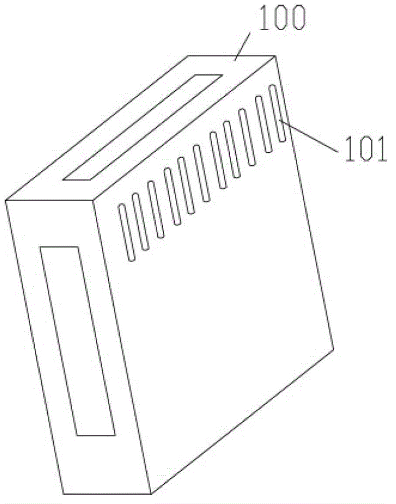
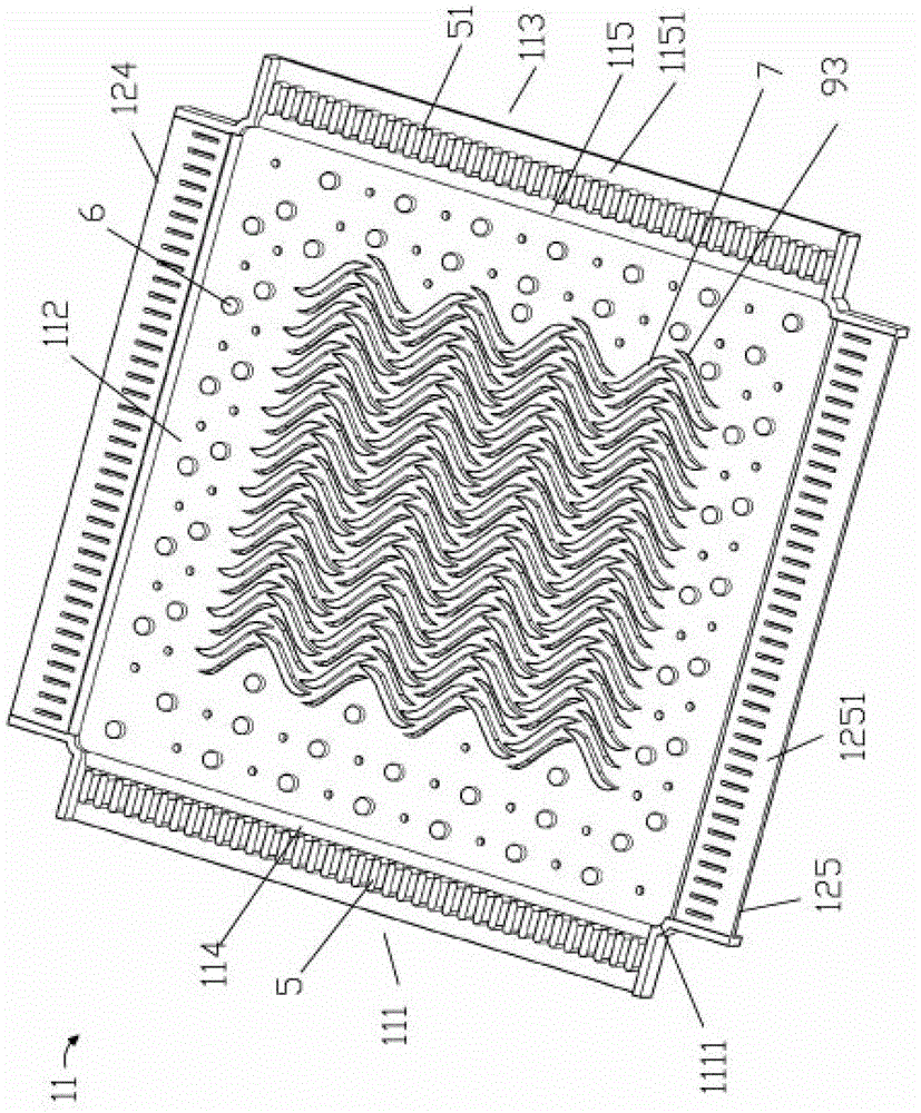
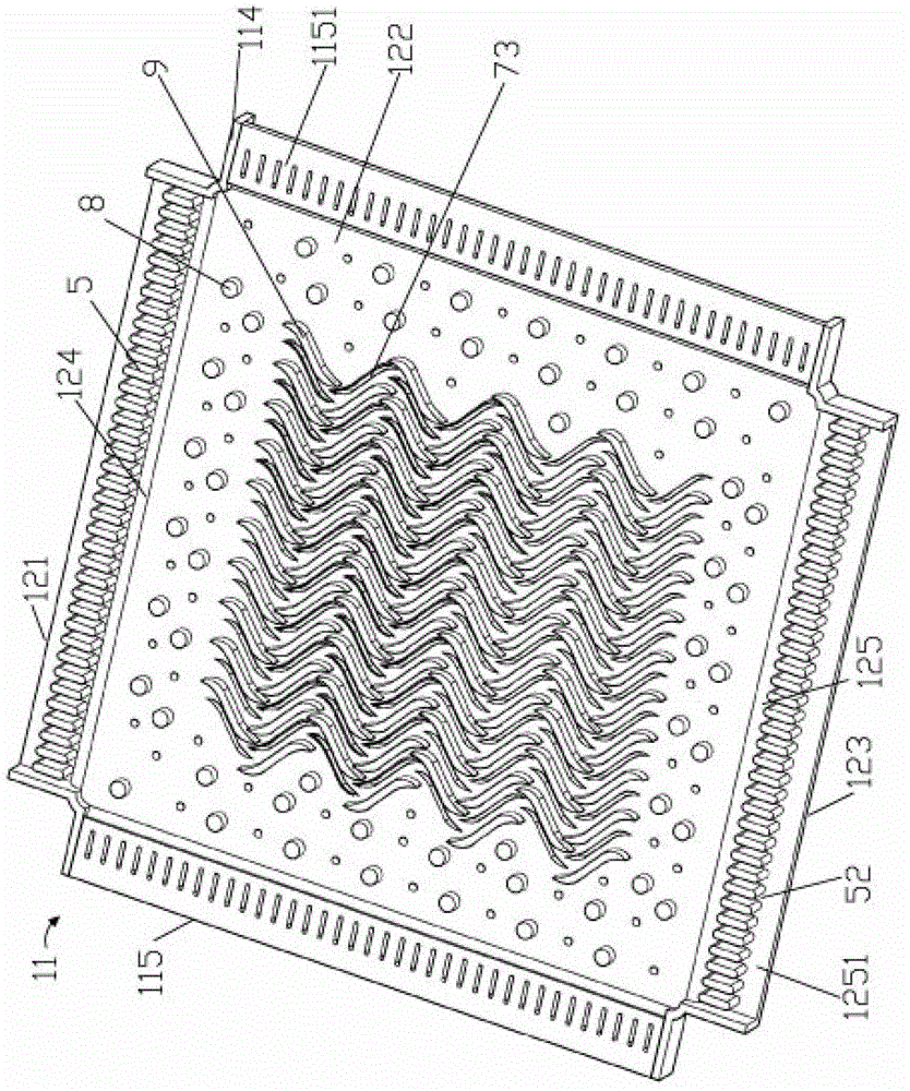
[0038] Example: see Figure 1 to Figure 10 As shown, a new type of heat exchanger with a microchannel heat exchange plate includes a heat exchanger shell 100 and a heat exchange device. The heat exchanger shell 100 is provided with a heat exchange medium inlet 1, a heat exchange medium outlet 2, The refrigerant inlet 3 and the refrigerant outlet 4, the heat exchange device consists of a partition 12 between two adjacent microchannel heat exchange plates 11 up and down, multiple microchannel heat exchange plates 11 and multiple partitions 12 The micro-channel heat exchange plate 11 is formed with multiple interwoven mesh grooves on both the front and back sides of the micro-channel heat exchange plate 11, and the left and right sides of the micro-channel heat exchange plate 11 face downwards. The left end flap 114 and the right end flap 115 are formed by bending. The upper and lower sides of the microchannel heat exchange plate 11 are bent upward to form the upper end flap 124 a...


PUM

PropertyMeasurementUnit
Thicknessaaaaaaaaaa
Thicknessaaaaaaaaaa

Abstract

The invention discloses a novel heat exchanger provided with a micro channel heat exchange plate, relating to the technical field of heat exchangers. The novel heat exchanger comprises a heat exchanger housing and a heat exchange device, wherein a heat exchange medium inlet, a heat exchange medium outlet, a refrigerant inlet and a refrigerant outlet are formed in the heat exchanger housing; the left side and the right side of the micro channel heat exchange plate of the heat exchange device are downwards bent to form a left end folded plate and a right end folded plate; the upper side and the lower side of the micro channel heat exchange plate are upwards bent to form an upper end folded plate and a lower end folded plate; baffles are welded and fixed at the four corners of the micro channel heat exchange plate; one side of each baffle is welded and fixed at the lateral side of the left end folded plate or the right end folded plate in the way of atomic diffusion; and the other side of the baffle is welded and fixed at the lateral side of the upper end folded plate or the lower end folded plate in the way of atomic diffusion. The novel heat exchanger provided with the micro channel heat exchange plate is very simple in structure, and convenient to manufacture; four access areas are as follows: a refrigerant inlet area, a refrigerant outlet area, a heat exchange medium inlet area and a heat exchange medium outlet area are arranged at the four directions of same micro channel heat exchange plate, so that the heat exchange effect is good and the connection is convenient.

Description

Technical field: [0001] The invention relates to the technical field of heat exchangers, in particular to a novel heat exchanger with microchannel heat exchange plates. Background technique: [0002] Existing heat exchangers are mostly finned copper tube, shell and tube, and plate heat exchangers. At present, the popular microchannel heat exchangers are formed based on air cooling. The increasingly stringent requirements for performance and volume have made it a trend for microchannel heat exchangers to gradually replace plate heat exchangers. Existing microchannel heat exchangers usually include several layers or the entire layer with refrigerant channels formed. The refrigeration heat exchange layer is formed with working fluid channels in several layers, and is stacked with the refrigeration heat exchange. The channel and the working fluid channel are arranged on the same plate, the second fluid channel and the first fluid channel arranged at intervals are formed on the ...

Claims


Application Information

Patent Timeline
IPC IPC(8): F28D9/00F28F3/12
Inventor 董永梅
Owner 董永梅
Why Eureka
Try Eureka