Multi-mode antenna for satellite navigation

A multi-mode satellite and antenna technology, applied in the field of radar electronic systems, can solve problems such as broadband and low profile, and achieve the effects of high gain at low elevation angle, wide antenna beam width, and good elevation-axis ratio characteristics.

Inactive Publication Date: 2013-02-06
XIDIAN UNIV
View PDF2 Cites 13 Cited by
  • Summary
  • Abstract
  • Description
  • Claims
  • Application Information

AI Technical Summary

Problems solved by technology

[0005] The purpose of the present invention is to overcome the deficiencies of the two antenna forms commonly used in satellite navigation systems, and propose a multi-mode satellite navigation antenna. Antenna Design Issues with Low Profile, Wide Angle of Elevation to Axis Ratio, and Wide Beam Coverage

Method used


Image

  • Multi-mode antenna for satellite navigation
  • Multi-mode antenna for satellite navigation
  • Multi-mode antenna for satellite navigation

Examples


Embodiment Construction

[0032] The technical solutions of the present invention will be further described below in conjunction with the accompanying drawings and specific embodiments.

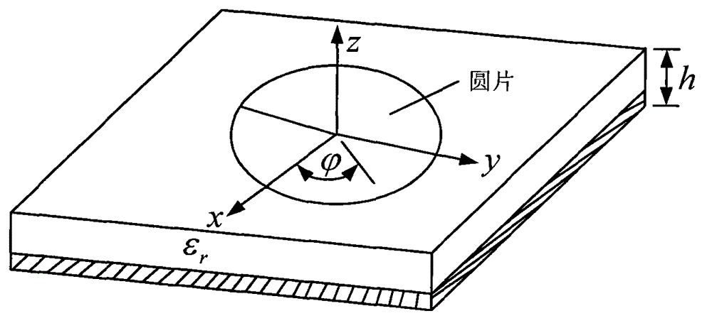
[0033] The invention applies the working principle of microstrip antenna and multi-feed point circular polarization. Such as figure 1 As shown, the circular patch antenna is a thin conductive circular patch on a dielectric substrate, and the back of the substrate is the floor. The electric field in the substrate basically has only z components, while the magnetic field has only x and y components. Because h0 , so the field is constant along the z direction, and the normal current component at the edge of the microstrip is close to zero at the edge. This means that the tangential component of the magnetic field goes to zero at the edge. Based on these assumptions, the circular microstrip antenna can be modeled as a cylindrical cavity. The upper and lower bottom surfaces are electric walls, and the side surfaces are...


PUM


Abstract

The invention discloses a multi-mode antenna for satellite navigation. The integral multi-mode antenna is divided into a first layer, a second layer, a third layer, a fourth layer and a fifth layer which are sequentially arranged from top to bottom. The first layer is a radiating layer and is of a double-layer short-circuit patch structure, an upper-layer patch of the radiating layer is positioned on the top of a first layer of dielectrics, and a lower-layer patch is positioned at the bottom of the first layer of dielectrics and is connected with the upper-layer patch by a short-circuit arm; the second layer is a dielectric layer for supporting the radiating layer and is positioned between a feed probe and the lower-layer patch; the third layer is an L-shaped probe feed layer and comprises four L-shaped probes, a horizontal portion of the third layer is printed on a dielectric layer, and a perpendicular portion of the third layer penetrates through the dielectric layer to be connected with a secondary feed network; the fourth layer is a secondary dielectric strip-line feed network layer and comprises two broadband 90-degree phase shifters; the fifth layer is a primary dielectric strip-line feed network layer and comprises a broadband 180-degree phase shifter; and the fourth layer is connected with the fifth layer by a metal probe. The antenna has the advantages of good low-elevation axial ratio characteristic and high multi-path interference resistance.

Description

technical field [0001] The invention belongs to the technical field of radar electronic systems, and relates to a multi-mode satellite navigation antenna, in particular to a multi-mode satellite navigation antenna with wide frequency band, miniaturization, wide beam, and wide-angle elevation angle ratio. Background technique [0002] In today's society, the rapid development of science and technology has brought the electronic information age ahead of schedule. In the positioning and navigation system, the traditionally used land-based radio navigation system is difficult to support the high-precision positioning and navigation of navigation, aviation, land vehicles and military in modern society because of its limited signal range and low positioning accuracy. Require. For this reason, satellite navigation systems with high positioning accuracy and fast speed have developed rapidly. [0003] With the popularization of the rapidly developing satellite positioning and navig...

Claims


Application Information

Patent Timeline
Patent Type & Authority Applications(China)
IPC IPC(8): H01Q25/04H01Q1/38H01Q13/08
Inventor 栗曦杨林郑会利傅光
Owner XIDIAN UNIV
Why Eureka
Try Eureka