Repetition frequency voltage-multiplying square-wave generator based on magnetic switch
A square wave generator, repetition frequency technology, applied in pulse train generator, pulse generation, electric pulse generation and other directions, can solve problems such as difficulty in adapting to development needs, and achieve the effect of reducing volt-second product requirements and fast charging
- Summary
- Abstract
- Description
- Claims
- Application Information
AI Technical Summary
Problems solved by technology
Method used
Image
Examples
Embodiment 1
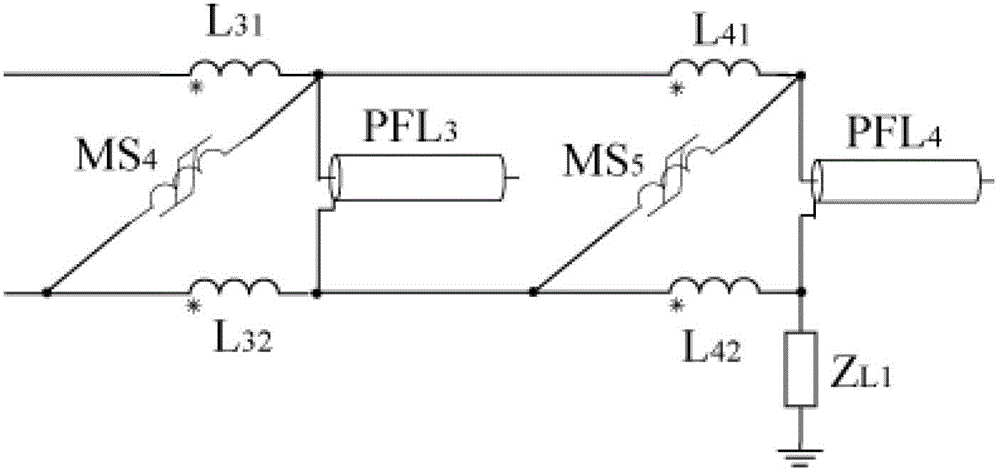
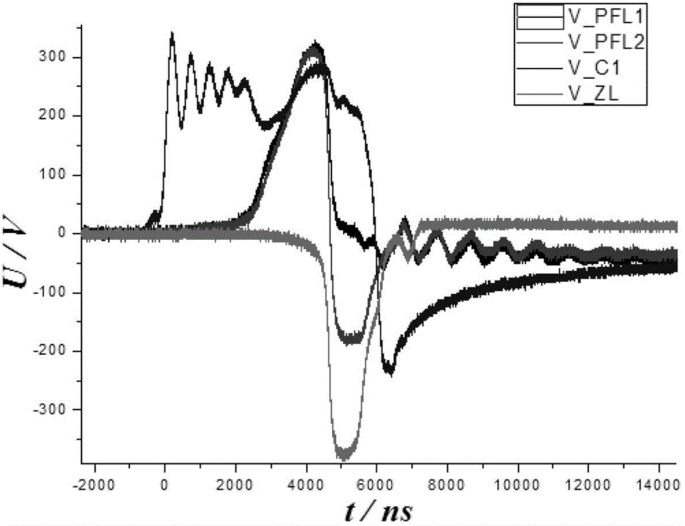
[0045] see figure 1 , figure 2 , forming a linear typical Marx generator based on a magnetic switch, including a pulse source with adjustable frequency pulse width; a magnetic pulse compression circuit; forming a linear Marx generator based on a magnetic switch; matching load four parts, among which the linear Marx generator The structure is:
[0046] N-level PFLs are charged in parallel, and the shielding layer (skin) and core port at one end of each level of PFL are connected to the circuit through a pair of coupled inductors, and the pair of coupled inductors is connected to the PFL with the same name, N-level PFL and its coupled inductor The relevant parameters of the pair should be exactly the same, and the direction of the same-named end of the coupled inductor on each side of the N-level PFL circuit should be consistent. The connection method of all levels of PFLs discharged in series through magnetic switches is as follows: the charging current inflow terminal of th...
Embodiment 2
[0053] Figure 5 Shown is the circuit topology diagram of the two-stage forming line charging and discharging port isolation type Marx generator. Compared with the circuit topology of the two-stage forming line type Marx generator based on magnetic switches, the connection method of the magnetic switch is changed: PFL 5 with PFL 6 The first end is connected to the circuit through a coupled inductor, and the tail end is connected in series through a magnetic switch to discharge to a matching load.
[0054] The connection method of the magnetic switch at the end is as follows: the wire core at the end of the first-stage PFL is grounded through MS7, and the end wire sheath of the n-stage PFL is connected to the end wire core of the n+1-stage PFL through a magnetic switch. The small inductance of the coupling inductance during the charging process is equivalent to a short circuit, the large inductance of the magnetic switch is equivalent to an open circuit, and the Marx generator...
Embodiment 3
[0057] Figure 6 Shown is the circuit topology of the two-stage magnetic switch parallel charging type Marx generator. Compared with the circuit topology of the two-stage magnetic switch-based linear Marx generator, the positions of the magnetic switch and the PFL are reversed. Magnetic switch MS through a coupled inductance 10 -MS 12 Perform parallel charging.
[0058] The advantage of the two-stage magnetic switch parallel charging type Marx generator is that the original circuit topology works as the magnetic switch MS 10 -MS 12 Impedance and PFL 9 -PFL 10 The impedance is relatively small, and the MS 10 -MS 12 A large current will flow, causing the current flowing through each coupled inductor to be different, so that the magnetic flux is unbalanced, and the PFL 9 -PFL 10 Charging consistency becomes poor. Figure 6 When a large current flows through the magnetic switch, the topological structure will improve the magnetic flux balance of the coupled inductor, the...
PUM
 Abstract
Description
Claims
Application Information
 - R&D
- Intellectual Property
- Life Sciences
- Materials
- Tech Scout
- Unparalleled Data Quality
- Higher Quality Content
- 60% Fewer Hallucinations
Browse by: Latest US Patents, China's latest patents, Technical Efficacy Thesaurus, Application Domain, Technology Topic, Popular Technical Reports.
© 2025 PatSnap. All rights reserved.Legal|Privacy policy|Modern Slavery Act Transparency Statement|Sitemap|About US| Contact US: help@patsnap.com


