Heat-conducting pad, method for manufacturing heat-conducting pad, radiating device and electronic device

A heat conduction pad and thermal conductivity technology, applied in heat exchange equipment, lighting and heating equipment, cooling/ventilation/heating transformation, etc., can solve the problems of high viscosity of heat conduction gel, application, heat conduction gel cannot pass through dispensing process, etc. , to achieve the effect of improving heat dissipation performance and good thermal conductivity

Active Publication Date: 2013-02-06
HUAWEI TECH CO LTD
View PDF2 Cites 63 Cited by
  • Summary
  • Abstract
  • Description
  • Claims
  • Application Information

AI Technical Summary

Problems solved by technology

A higher thermal conductivity means a higher content of thermally conductive fillers, which can lead to too high a viscosity of the thermally conductive gel
The viscosity of the thermally conductive gel is too high, which will cause the thermally conductive gel to be applied by the dispensing process, which is not suitable for industrial batch processing and production
[0009] Therefore, as the power density of heat-generating components in electronic equipment continues to rise, the power density of single boards continues to rise, and the requirements for the thermal conductivity of interface heat-conducting materials are getting higher and higher. To meet the heat dissipation requirements of some high-performance electronic equipment, the temperature rise between the heat-generating components and the radiator is too high to become a heat dissipation bottleneck

Method used


Image

  • Heat-conducting pad, method for manufacturing heat-conducting pad, radiating device and electronic device
  • Heat-conducting pad, method for manufacturing heat-conducting pad, radiating device and electronic device
  • Heat-conducting pad, method for manufacturing heat-conducting pad, radiating device and electronic device

Examples


Embodiment Construction

[0046] The following will clearly and completely describe the technical solutions in the embodiments of the present invention with reference to the drawings in the embodiments of the present invention. Obviously, the described embodiments are part of the embodiments of the present invention, not all of them. Based on the embodiments of the present invention, all other embodiments obtained by persons of ordinary skill in the art without making creative efforts shall fall within the protection scope of the present invention.

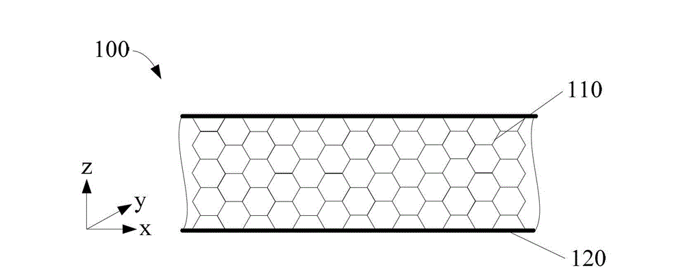
[0047] figure 1 A schematic cross-sectional view of the thermal pad 100 according to an embodiment of the present invention is shown. Such as figure 1 As shown, the thermal pad 100 includes:

[0048] A thermally conductive sheet-like substrate 110 having a compressible porous network structure in the thickness direction; and

[0049] a thermally conductive coating 120 formed from a flexible organic compound,

[0050] Wherein, the organic compound is fi...


PUM

PropertyMeasurementUnit
compressive stressaaaaaaaaaa

Abstract

The embodiment of the invention discloses a heat-conducting pad, a method for manufacturing the heat-conducting pad, a radiating device and an electronic device. The heat-conducting pad comprises a heat-conducting sheet base material, and a heat-conducting coating layer; the sheet base material has a compressible porous reticular structure in a thickness direction; the coating layer is formed by a flexible organic compound; the organic compound is filled inside the sheet base material or covered on the surface of the sheet base material, or the organic compound is covered on the surface of the sheet base material when being filled inside the sheet base material. According to the heat-conducting pad, the method for manufacturing the heat-conducting pad, the radiating device and the electronic device, by adopting the flexible heat-conducting organic compound, or the heat-conducting sheet base material with the compressible porous reticular structure filled or covered in the thickness direction, the formed heat-conducting pad has good heat-conducting property and also has a good compression performance. Thus, the heat transfer performance of the electronic device can be improved.

Description

technical field [0001] The invention relates to the field of electronic equipment, in particular to a heat conduction pad in the field of electronic equipment, a method for manufacturing the heat conduction pad, a heat dissipation device and electronic equipment. Background technique [0002] The heat generated by the operation of chips in electronic equipment usually requires the use of heat sinks to spread the heat to the outside. From a microscopic point of view, there are a lot of unevenness in the contact interface between the chip and the heat sink. It is necessary to use interface heat-conducting materials to fill the contact interface between the chip and the heat sink to reduce the contact thermal resistance. Interface thermally conductive materials usually include thermally conductive silicone grease, thermally conductive pads, thermally conductive gels, phase change thermally conductive materials, thermally conductive double-sided tapes, etc. According to differen...

Claims


Application Information

Patent Timeline
Patent Type & Authority Applications(China)
IPC IPC(8): H05K7/20
CPCB23P15/26H01L23/34F28F3/00G06F1/20H01L23/373H01L23/3733H01L23/3737H01L2924/0002Y10T29/4935H01L2924/00
Inventor 徐焰涂运骅
Owner HUAWEI TECH CO LTD
Why Eureka
Try Eureka