Dual-polarization radiating element of a multiband antenna
A radiating element and dual-polarization technology, applied in the structural form of radiating elements, antenna components, independent antenna unit combinations, etc., can solve problems such as difficulty, inability to use reflectors, and reduction of surface area
- Summary
- Abstract
- Description
- Claims
- Application Information
AI Technical Summary
Problems solved by technology
Method used
Image

Examples
Embodiment Construction
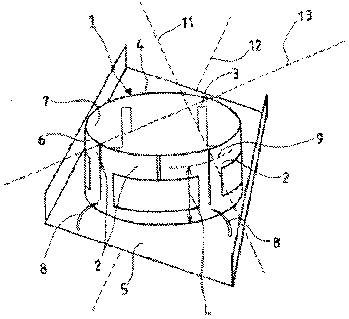
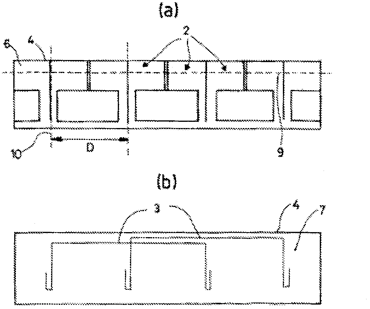
[0041] exist figure 1 , 2 In the first embodiment shown in a and 2b, the dual-polarized radiating element 1 is formed by two half-wave dipoles 2, and each dipole includes a conductive feeder 3. The dipole 2 is supported by a shared support 4 fixed to a reflector 5 . The radiating element 1 is constructed by forming the shared support 4 into a cylindrical shape. The cylindrical support 4 thus obtained is then placed on a shared planar reflector 5 with a plurality of radiating elements 1 in a perpendicular manner.
[0042] In this example embodiment, the dipoles 2 are printed on the first outer surface 6 of the shared support 4 . Each dipole 2 is fed by a wire 3 located on the second inner surface 7 of the support 4 . Of course, it is possible to print the dipoles on the inner surface and the feed lines on the outer surface. The conductive feed 3 is, for example, a "microstrip" printed directly on the support 4 . This shared support 4, whose circumference is about 2 wavel...
PUM
 Abstract
Description
Claims
Application Information
PatSnap Eureka turns technology decisions into work you can execute. Powered by our Innovation Knowledge Graph, it runs expert workflows across engineering, life sciences, materials and intellectual property. Get your review-ready output in minutes.


