Automatic device for machining two ends of shaft parts

A technology of shaft parts and automatic devices, applied in positioning devices, metal processing equipment, metal processing machinery parts, etc., can solve the problems of low labor productivity, universality of workpieces, inability to be universal, and inapplicability, etc., to achieve universality difficult problems, improve labor productivity, and solve the effect of low productivity

Active Publication Date: 2013-02-13
宁波精益微型轴有限公司
View PDF5 Cites 25 Cited by
  • Summary
  • Abstract
  • Description
  • Claims
  • Application Information

AI Technical Summary

Problems solved by technology

Its advantages are: loading materials at one time, processing both ends at the same time, saving auxiliary time; its disadvantages are that it is a special equipment and cannot be used universally, and it cannot be used when the length of the shaft parts changes, and the length of the shaft parts is shorter than the length of the headstock. not applicable
[0007] How to solve the long time-consuming transmission process of shaft parts, resulting in low labor productivity and how to solve the common problem of automatic processing equipment for processing workpieces have become two major technical problems that technicians in this industry urgently need to solve

Method used


Image

  • Automatic device for machining two ends of shaft parts
  • Automatic device for machining two ends of shaft parts
  • Automatic device for machining two ends of shaft parts

Examples


Embodiment Construction

[0044] Each reference sign name among the accompanying drawings is:

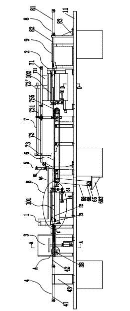
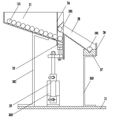
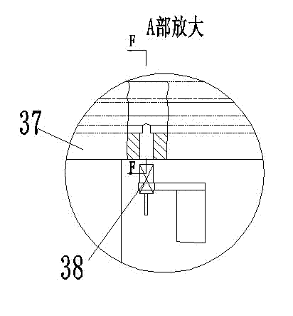
[0045] The first lathe 1, the second lathe 2, the machine body 21, the dovetail groove 211, the nut 22, the base 23, the screw rod 24, the adjustment screw 25, the inlay 26, the bin 3, the bin body 31, the bin cylinder 32, the pusher Device 33, baffle plate 34, chute 35, baffle plate 36, V-groove 37, photoelectric sensor 38, bracket 391, 392, 393, feeding mechanism 4, feeding cylinder 41, cylinder piston push rod 42, sleeve 421, Push post 422, spring 423, screw 424, gasket 425, support 43, positioning mechanism 5, positioning cylinder 51, support frame 52, support plate 53, transmission mechanism 6, driving round pulley 61, wheel body 611, mandrel 612, Rolling bearing 613, retaining ring 614, inner spacer 615, outer spacer 616, screw 617, driven round pulley 62, round belt 63, 64, motor 65, driving sprocket 66, driven sprocket 67, transmission chain 68, Supports 691, 692, 693, feeding positioning mechanism ...


PUM


Abstract

The invention discloses an automatic device for machining two ends of shaft parts. The automatic device comprises two numerically controlled lathes, wherein directions of headstocks of the two numerically controlled lathes are opposite and the two numerically controlled lathes are mounted on the central line on the same horizontal plane; and one numerically controlled lathe is fixedly mounted and the other numerically controlled lathe is mounted in a way of being capable of being movably adjusted. A shaft part semi-finished product conveying mechanism is arranged between the two lathes. The front end of the first lathe is provided with a material cabin of a shaft part blank material and a material conveying mechanism; the rear end of the first lathe is provided with a positioning mechanism; the two mechanisms are matched to place one end of the shaft part blank material at one end of a machining part for machining a work piece of the first lathe; the rear end of the second lathe is provided with a material conveying and positioning mechanism and the front end of the second lathe is provided with an auxiliary positioning mechanism and a shaft part finished product collector; and the two mechanisms are matched to place a machined shaft part semi-finished product on the other end of a machining part for machining the work piece of the second lathe. According to the automatic device disclosed by the invention, the continuous automatic production of the two lathes is realized and two difficulties in the prior art that the labor production rate is low and equipment has no generality are solved.

Description

technical field [0001] The invention relates to a machine for automatically processing parts, in particular to an automatic device for turning both ends of shaft parts. Background technique [0002] Turning of both ends of shaft parts, including turning both ends, chamfering and grooves, or turning the outer circle of the shaft end, etc. The methods currently used are as follows: [0003] The first is: the auxiliary process is manually operated. One end of the shaft part is processed on a CNC lathe first. After the processing is completed, the shaft part is taken out, turned 180 degrees, and then sent to the next CNC lathe to process the other end of the shaft part. Because the taking out, turning around and feeding of shaft parts all need to be done manually, so one person can only take care of two lathes, so the labor productivity is low. In addition, due to the large-scale processing and production of shaft parts, the labor intensity is high, and the monotonous repeate...

Claims


Application Information

Patent Timeline
Patent Type & Authority Applications(China)
IPC IPC(8): B23B15/00B23B5/16B23Q3/00
Inventor 董祥义
Owner 宁波精益微型轴有限公司
Why Eureka
Try Eureka