Ultra-short base line differential plate type optical fiber displacement sensor and optical fiber strain gauge

A displacement sensor and ultra-short baseline technology, applied in the field of strain gauges, can solve the problems of electromagnetic interference, output nonlinearity, and unsuitable strain gauges for long-term stable and reliable operation of the sensor, and achieve the effect of improving accuracy

Active Publication Date: 2013-02-13
HARBIN ENG UNIV
View PDF6 Cites 10 Cited by
  • Summary
  • Abstract
  • Description
  • Claims
  • Application Information

AI Technical Summary

Problems solved by technology

[0008] Displacement sensors currently invented in strain gauges mainly use eddy current displacement sensors, differential transformer displacement sensors, or capacitive displacement sensors, among which the best displacement resolution of the first two is about 1nm; , can reach 0.01nm, but there are shortcomings such as parasitic capacitance and distributed capacitance that have a great impact on sensitivity and measurement accuracy, output is nonlinear, connection circuit is complicated, and it is affected by humidity and electromagnetic interference, etc., it is not suitable for long-term stability and reliability of strain gauges. work needs

Method used


Image

  • Ultra-short base line differential plate type optical fiber displacement sensor and optical fiber strain gauge
  • Ultra-short base line differential plate type optical fiber displacement sensor and optical fiber strain gauge
  • Ultra-short base line differential plate type optical fiber displacement sensor and optical fiber strain gauge

Examples


Embodiment Construction

[0047] The present invention will be further described below in conjunction with the embodiments and drawings, but the protection scope of the present invention should not be limited by this.

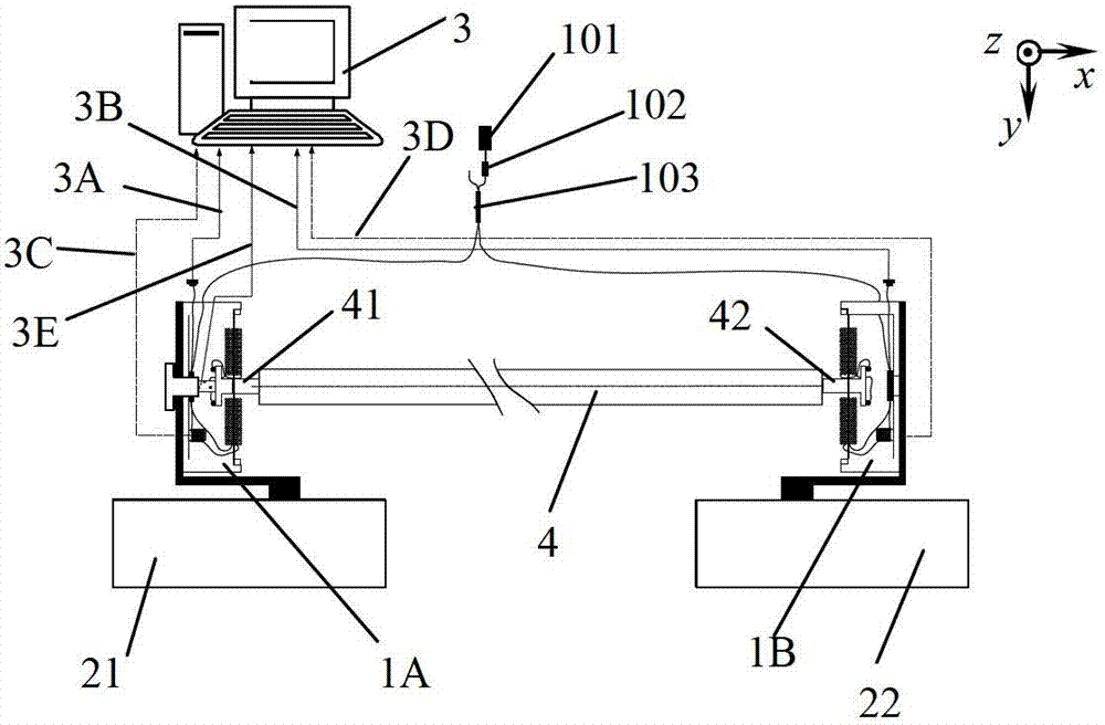
[0048] Combine figure 1 The optical fiber strain gauge of the present invention is composed of displacement sensors 1A, 1B, measurement baseline rod 4, measurement bedrock 21, 22, and measurement control and signal recording and processing system 3. The first optical fiber displacement is fixed on the first bedrock 21 The sensor 1A is connected to one end 41 of the measurement baseline 4; the second optical fiber displacement sensor 1B fixed on the second bedrock 22 is connected to the other end 42 of the measurement baseline 4; the locking knob 116 and the piezoelectric ceramic displacement generator constitute a displacement calibration device , And connected with the first optical fiber displacement sensor 1A; the first optical fiber displacement sensor 1A and the second optical fiber di...


PUM


Abstract

The invention provides an ultra-short base line differential plate type optical fiber displacement sensor and an optical fiber strain gauge. The ultra-short base line differential plate type optical fiber displacement sensor comprises an outer frame, wherein an outer ring of a displacement conversion device is tightly pressed on the outer frame by a pressing ring with external threads, a threaded pillar of a central press washer penetrates through a central hole in the displacement conversion device, and a first Faraday rotating mirror and a second Faraday rotating mirror are solidified on the central press washer; and an optical fiber coupler and a phase modulator are fixed on the surface of the inner wall of the outer frame, the outer frame and a fixed base are fixed, a first measurement optical fiber and a second measurement optical fiber are respectively wound into multilayered optical fiber loops with hollow plate type layered structures, the first measurement optical fiber and the second measurement optical fiber are respectively solidified on the upper surface and the lower surface of the displacement conversion device, the coupler is connected with the fist Faraday rotating mirror, the phase modulator and a detector, the fist measurement optical fiber is connected with the first Faraday rotating mirror, the phase modulator is connected with the second measurement optical fiber, and the second measurement optical fiber is connected with the second Faraday rotating mirror. The ultra-short base line differential plate type optical fiber displacement sensor and the optical fiber strain gauge are mainly used for observing earth crust strain and solid tide, and acquiring earthquake precursor information.

Description

Technical field [0001] The invention relates to an optical fiber sensing measurement device, in particular to an optical fiber displacement sensor used for geophysical research, observation of crustal strain and solid tides, and acquisition of earthquake precursor information, and a strain gauge mainly composed of optical fiber displacement sensors. Background technique [0002] Strain gauge is an instrument that accurately measures the relative change of the distance between two points in the crustal rock mass. It has important applications in the observation of crustal strain and solid tides, as well as in the study of earthquake incubation processes and the acquisition of earthquake precursors. [0003] Since the American seismologist H. Benioff developed the first valuable quartz extensometer in 1935, the United States, Britain, the former Soviet Union, Japan, Belgium, Germany and other countries have successively developed high-sensitivity extensometers. instrument. The sensi...

Claims


Application Information

Patent Timeline
Patent Type & Authority Applications(China)
IPC IPC(8): G01B11/02G01B11/16
Inventor 杨军彭峰吴冰苑勇贵苑立波
Owner HARBIN ENG UNIV
Why Eureka
Try Eureka