Magneto-optical switch

A magneto-optical switch and optical component technology, applied in optics, nonlinear optics, optical waveguide coupling, etc., can solve the problems of difficult packaging, scattering, and many devices, so as to reduce volume, reduce production cost, and reduce the number of devices little effect

Active Publication Date: 2013-02-13
ZHUHAI FTZ OPLINK COMM
View PDF3 Cites 9 Cited by
  • Summary
  • Abstract
  • Description
  • Claims
  • Application Information

AI Technical Summary

Problems solved by technology

[0008] However, since the optical fibers 12 and 24 installed in the single-fiber collimator 11 and the dual-fiber collimator 23 are common optical fibers, the spot diameter of the light beam exiting from the optical fiber 12 is large and the scattering is serious, resulting in the need to use a larger double-fiber collimator. Refractive crystal 13, the volume of Faraday rotator plate 16,19 and birefringent crystal light guide 17, birefringent crystal beam deflector 18 is all very big like this, and use roof prism as the situation of birefringent crystal 18, also need in A certain gap is set between the birefringent crystal light guide 17 and the birefringent crystal beam deflector 18, resulting in the Faraday rotator 16, 19 and the volume of the birefringent crystal light guide 17 and the birefringent crystal beam deflector 18 being difficult. made smaller
[0009] And, since the magnetic field generating devices 15, 20 generally comprise an iron core, and coils are wound on the iron core, due to the volume of the Faraday rotators 16, 19, the birefringent crystal light guide 17, and the birefringent crystal beam deflector 18 Larger, it is difficult to arrange the above-mentioned devices in the same iron core, and it is necessary to use two magnetic field generating devices 15, 20 to apply magnetic fields to the Faraday optical rotation plates 16, 19 respectively, resulting in more devices used in the magneto-optical switch, and the volume of the device Larger, so that the production cost of the magneto-optical switch is higher, and the packaging is more difficult

Method used


Image

  • Magneto-optical switch
  • Magneto-optical switch
  • Magneto-optical switch

Examples


no. 1 example

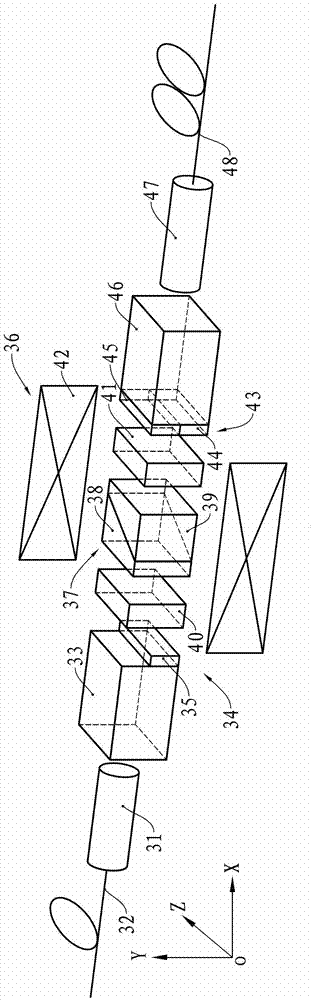
[0033] see figure 2 , the magneto-optical switch of this embodiment has a single-fiber collimator 31, and an optical fiber 32 is installed in the single-fiber collimator 31. In this embodiment, the single fiber collimator 31 is a single-core beam expanding fiber collimator, and the optical fiber 32 is a beam expanding fiber. At the exit end of the single-fiber collimator 31, a birefringent crystal 33, a half-wave plate assembly 34, an optical rotation assembly 36, a half-wave plate assembly 43, a birefringent crystal 46, and a double-fiber collimator 47 are sequentially arranged along the optical path direction, Two parallel optical fibers 48 are installed in the dual-fiber collimator 47, and the dual-fiber collimator 47 is a dual-core beam-expanding optical fiber collimator, and the two optical fibers 48 are both beam-expanding optical fibers.

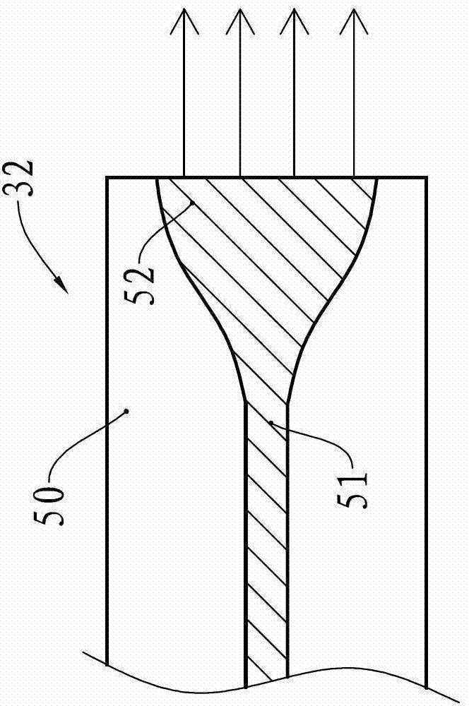
[0034] see image 3 , the expanded beam fiber 32 has a core 51 and a cladding 50 wrapped around the core 51, near the end of the ...

no. 2 example

[0059] see Figure 8 , this embodiment has a single-fiber collimator 61, and an optical fiber 62 is installed in the single-fiber collimator 61. At the exit end of the single-fiber collimator 61, a birefringent crystal 63, a half-wave plate assembly 64, an optical rotation assembly 67, a half-wave plate assembly 73, a birefringent crystal 76, and a double-fiber collimator 77 are sequentially arranged along the optical path direction, Two parallel optical fibers 78 are installed in the double fiber collimator 77 .

[0060] The single-fiber collimator 61 is a single-core beam-expanding fiber collimator, the double-fiber collimator 77 is a dual-core beam-expanding fiber collimator, and the optical fibers 62 and 78 are both beam-expanding optical fibers, that is, the fibers near the end of the optical fiber. The core diameter expands rapidly so that the spot diameter of the beam emerging from the optical fiber 62 is large.

[0061] The half-wave plate assembly 64 has two half-wa...


PUM


Abstract

The invention provides a magneto-optical switch. The magneto-optical switch comprises a single-fiber collimator, a first birefringent crystal, a first half-wave plate component, an optical rotation component, a second half-wave plate component, a second birefringent crystal and a dual-fiber collimator which are sequentially arranged in the optical path direction, wherein the optical rotation component is provided with a refractor; a first Faraday optical rotation piece is arranged on the side of the refractor close to the first half-wave plate component; an optical rotation device is arranged on the side of the refractor close to the second half-wave plate component; the optical rotation component is further provided with a magnetic field producer positioned outside the first Faraday optical rotation piece; the single-fiber collimator is a single-core beam-expanding fiber collimator with a beam-expanding optical fiber mounted therein; and the dual-fiber collimator is a dual-core beam-expanding fiber collimator with two beam-expanding optical fibers mounted therein. The magneto-optical switch provided by the invention adopts smaller devices, and the birefringent crystals and the optical rotation component are both small in size, so that the size of the magneto-optical switch is reduced and the manufacturing cost of the magneto-optical switch is lowered.

Description

technical field [0001] The invention relates to an optical device used in an optical fiber communication system, in particular to a magneto-optical switch. Background technique [0002] Various optical switches are widely used in modern fiber optic communication systems to realize the switching of light beams between one input fiber and multiple output fibers or between multiple input fibers and one output fiber. It is mainly used in modern fiber optic communication industry, instrumentation industry and defense industry. [0003] Common optical switches are mainly divided into mechanical optical switches and non-mechanical optical switches, which apply micro-optical electromechanical technology (MEMS), liquid crystal technology, thermo-optic effect, electro-optic technology and magneto-optical technology. Among them, the mechanical optical switch technology is relatively mature, which has the advantages of low production cost, wide bandwidth, and low loss, but at the same ...

Claims


Application Information

Patent Timeline
Patent Type & Authority Applications(China)
IPC IPC(8): G02F1/095
CPCG02F1/09G02F1/31G02B6/26
Inventor 胡宇赵泽雄孙先胜邱炳龙龚森明
Owner ZHUHAI FTZ OPLINK COMM
Why Eureka
Try Eureka