Supercharge Your Innovation With Domain-Expert AI Agents!

Color display element manufacturing method and color display element

A technology of color display and manufacturing method, which is applied in the direction of electrical components, optical components, instruments, etc., can solve the problems of low light utilization efficiency, waste of process cost coloring resist, damage to brightness, etc.

Inactive Publication Date: 2013-02-13
NIPPON STEEL CHEM & MATERIAL CO LTD +1
View PDF13 Cites 5 Cited by
  • Summary
  • Abstract
  • Description
  • Claims
  • Application Information

AI Technical Summary

Problems solved by technology

In addition, the conventional paper medium is naturally full-color display, and expectations for the colorization of electronic paper are very high
[0003] As the technology of electronic paper capable of color display that has been proposed so far, for example, a medium in which a color filter is formed in a reflective liquid crystal element has been commercialized, but since a polarizer is used, the light utilization efficiency is low, and only darker white display
In addition, because black cannot be displayed, the contrast is also poor
[0004] In addition, there is an electrophoretic method as a bright reflective display element. The principle of the electrophoretic method is to move charged white particles and black particles by an electric field. However, the scattering reflectance of the white particles in this electrophoretic method is less than 40% at most, and it is desired to further improve the reflection. efficiency
Among them, the superimposition of color filters or colored pixels with a black matrix used in conventional liquid crystal display devices, etc., leads to impairment of luminance
In addition, in Patent Document 1, when realizing a multi-color display element, colored pixels are formed by photolithography the same number of times as the number of colored layers, so the process cost and colored resist are wasted.

Method used


Image

  • Color display element manufacturing method and color display element
  • Color display element manufacturing method and color display element
  • Color display element manufacturing method and color display element

Examples


Embodiment 1

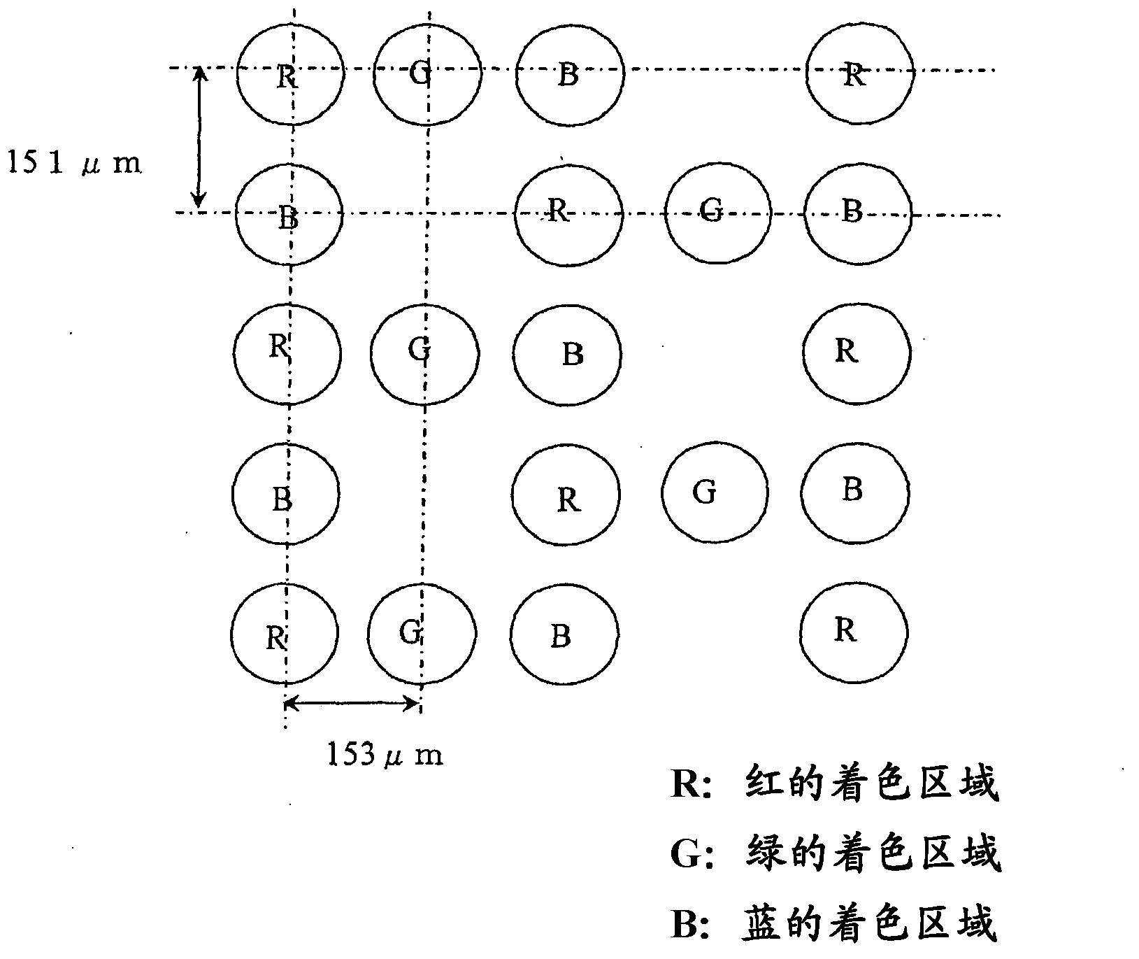
[0079] Using an inkjet head KM512L manufactured by Konica Minolta (equipped with nozzles 512 holes capable of discharging 42 pl), the aforementioned colored inkjet inks R1, G1, and B1 were applied on a PET film for inkjet produced by Toyobo as a transparent support substrate (model number GT701#130) above as image 3 A color filter of 6 inches was produced by drawing at a pitch as shown to obtain a colored area. After drawing, drying was performed at 80° C. for 3 minutes on a hot plate, 1500 mJ (I-ray standard) exposure was performed with an ultraviolet exposure machine, and firing was performed at 140° C. for 30 minutes. The diameter and height of each droplet during processing are measured. The overlapping of the three colors was not seen at all, and the convex shape was shown as shown in Table 3, and the area of ​​the colored region was 90% or less with respect to the pixel electrode of the TFT substrate.

[0080] [table 3]

[0081]

Embodiment 2 and Embodiment 3

[0083] In addition to drawing each colored ink twice at the same position by overlapping the same dotted position as in Example 1 (Example 2), or by drawing 3 times and drawing by 3 drops Except for (Example 3), color filters were produced in the same manner as in Example 1 (Table 4). It can be seen that the convex shape is shown without overlapping in any of the colors, and that the height becomes higher as the number of drops increases. In addition, the area of ​​the colored region is 90% or less with respect to the pixel electrode of the TFT substrate.

[0084] [Table 4]

[0085]

Embodiment 4

[0087] A 6-inch color filter was produced in the same manner as in Example 1 except that a 0.7 mm-thick alkali-free glass plate (AN-100 manufactured by Asahi Glass Co., Ltd.) was used as the transparent support substrate (Table 5). It can be seen that colored pixels are formed without overlapping in any color. In addition, the area of ​​the colored region is 90% or less with respect to the pixel electrode of the TFT substrate.

[0088] [table 5]

[0089]


PUM

PropertyMeasurementUnit
water contact angleaaaaaaaaaa
particle diameteraaaaaaaaaa
surface tensionaaaaaaaaaa

Abstract

Disclosed is a color display element manufacturing method that provides a conventional black-and-white digital paper format as a simple and inexpensive color display element without reduced brightness. In a color display element, charged display bodies, comprising black and white colors, are sealed between a pair of opposing substrates comprising electrodes, and one of the pair of opposing substrates is provided with a color filter. The color filter, disposed on the viewing side, first forms at least red, green, and blue color regions upon a transparent support substrate with inkjet techniques, and regions other than the color regions are treated as either colorless or transparent.

Description

technical field [0001] The present invention relates to a display element, in particular to an element structure of a reflective color display, and to a technology using electronic paper. Background technique [0002] Electronic paper is actively being developed as an electronic medium that replaces paper. Compared with CRT and liquid crystal displays, which are conventional displays, the characteristics necessary for electronic paper include: it is a reflective display element, it has high white reflectivity, high contrast, it has a memory effect in display, and it can Driven by low voltage, thin and light, and high quality and low price. In particular, white reflectance and / or contrast of the same quality as paper are required as display properties. In addition, the conventional paper medium is naturally full-color display, and expectations for colorization of electronic paper are very high. [0003] As the technology of electronic paper capable of color display that ha...

Claims


Application Information

Patent Timeline
Patent Type & Authority Applications(China)
IPC IPC(8): G02F1/167G02B5/20G02F1/1677
CPCH05B33/10G02F1/167G02F2201/52G02B5/201G02F1/1677G02B5/20G02F2202/04
Inventor 藤城光一板原俊英斋藤亨浦野和久井口真介汲田健太郎滝田友春
Owner NIPPON STEEL CHEM & MATERIAL CO LTD
Features
  • R&D
  • Intellectual Property
  • Life Sciences
  • Materials
  • Tech Scout
  • Unparalleled Data Quality
  • Higher Quality Content
  • 60% Fewer Hallucinations
Learn More