
Heater of ingot furnace

A technology for heaters and ingot casting furnaces, applied in chemical instruments and methods, crystal growth, and self-melting liquid pulling methods, etc., can solve incomplete melting, quasi-single crystal area becomes smaller, and protect seed crystals from incomplete melting, etc. problem, to achieve the effect of increasing the crystal growth rate, good single crystal area, and less geometric space

Active Publication Date: 2013-02-20
JIANGSU XIEXIN SILICON MATERIAL TECH DEV +1
View PDF5 Cites 10 Cited by
  • Summary
  • Abstract
  • Description
  • Claims
  • Application Information

AI Technical Summary

Problems solved by technology

The production of ingot monocrystalline silicon is mainly through the following methods: lay a layer of 5-40mm single crystal seed crystal on the bottom of the quartz crucible when charging, and then fill the polycrystalline silicon raw material, protect the bottom seed crystal from being completely melted during the melting process, and then Single crystal silicon growth is carried out on the basis of unmelted seed crystals; the main difficulty of this method is to protect the seed crystals from incomplete melting during the melting process, however, in the production of existing ingot casting furnaces, when the thermal insulation cage is closed and the raw material is in the During the melting process, the temperature distribution in the thermal field is relatively uniform, and the seed crystal cannot be well protected
In addition, it is difficult to obtain a flat isothermal surface only by lifting the insulation cage. In practice, it is mostly a concave solid-liquid interface, which will lead to a gradual reduction of the quasi-single crystal region.

Method used


Image

  • Heater of ingot furnace
  • Heater of ingot furnace
  • Heater of ingot furnace

Examples


Embodiment Construction

[0030] The following are specific embodiments of the present invention, which further describe the technical solutions of the present invention, but the present invention is not limited to these embodiments.

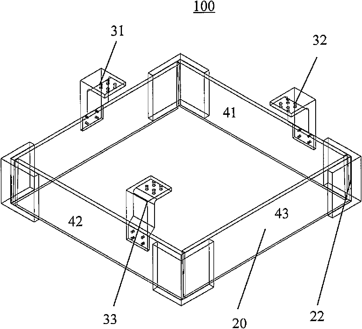
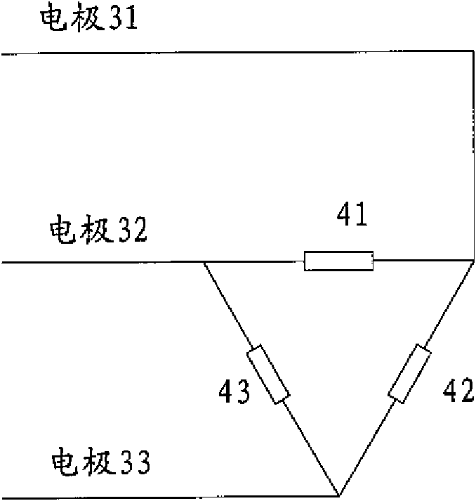
[0031] figure 1 A heater 100 is shown, which is a resistance heater formed by connecting a plurality of heating blocks through connecting plates and adding electrodes thereon. Specifically, the four heating blocks 20 are connected together by connecting plates 22 to form a circumferential closed structure. Wherein, the heating blocks 20 are all made of the same carbon-carbon composite material, and the connecting plate 22 is made of graphite or carbon-carbon composite material. The above-mentioned circumferential closed structure is equipped with electrodes 31, 32 and 33 and is divided into three sections of resistance by them, that is, the heat generating body part 41 between the electrodes 31 and 32, the heat generating body part between the electrodes 31 and 33 The ...


PUM


Abstract

The invention discloses a heater of an ingot furnace. The heater is composed of a first electrode, a second electrode and a heat generating body located between the first electrode and the second electrode. Specifically, the heat generating body is in electric connection with the first electrode and the second electrode respectively; the first electrode and the second electrode are used for directly or indirectly connecting a power source so as to make an electric current formed in the heat generating body located between the first electrode and the second electrode; the heat generating body extends along a longitudinal direction and / or a radial direction to at least partially surround the lateral side and / or the end of a crucible, wherein the heat generating body is used for forming a temperature-grading thermal field. The heater itself has small geometric space occupation and light weight, can generate a temperature field in graded distribution, and can improve the crystal growth speed. In addition, the heater has good effects on seed crystal protection and planar solid-liquid interface providing in single-crystal-like ingotting technologies so as to enlarge a single-crystal region.

Description

technical field [0001] The invention belongs to the technical field of design and manufacture of an ingot furnace, and in particular relates to a heater for an ingot furnace. Background technique [0002] Solar photovoltaic power generation is one of the forms of sustainable energy utilization, and it has developed rapidly in various countries in recent years. At present, crystalline silicon solar cells are the most widely used, and crystalline silicon solar cells are mainly made of single crystal silicon wafers or polycrystalline silicon wafers. In the world's photovoltaic industry, polysilicon wafers occupy a dominant position in solar cells due to their high production capacity, low energy consumption, and low cost. The ingot furnace is the core manufacturing equipment for producing polysilicon ingots. [0003] Chinese patent application CN101775641A discloses the structure of a polycrystalline silicon ingot furnace, which includes a furnace chamber, a crucible placed in...

Claims


Application Information

Patent Timeline
IPC IPC(8): C30B15/18C30B28/06C30B29/06C30B35/00
Inventor 杨细全薛抗美胡亚兰
Owner JIANGSU XIEXIN SILICON MATERIAL TECH DEV
Learn More