Device for calibrating dynamic balance parameter of helicopter rotor blade
A technology for helicopter rotor and parameter calibration, which is applied in static/dynamic balance testing, measuring device, machine/structural component testing, etc., and can solve problems such as poor reliability and measurement result error.
- Summary
- Abstract
- Description
- Claims
- Application Information
AI Technical Summary
Problems solved by technology
Method used
Image
Examples
specific Embodiment approach 1
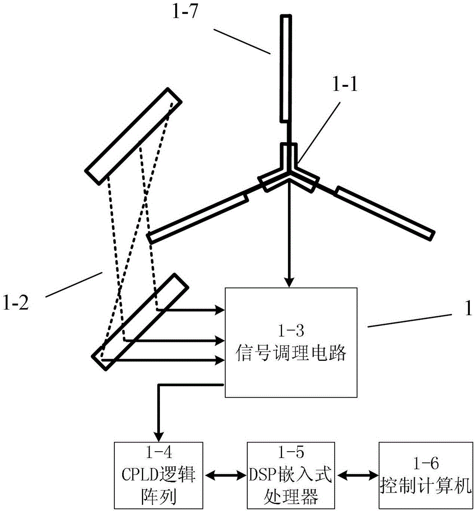
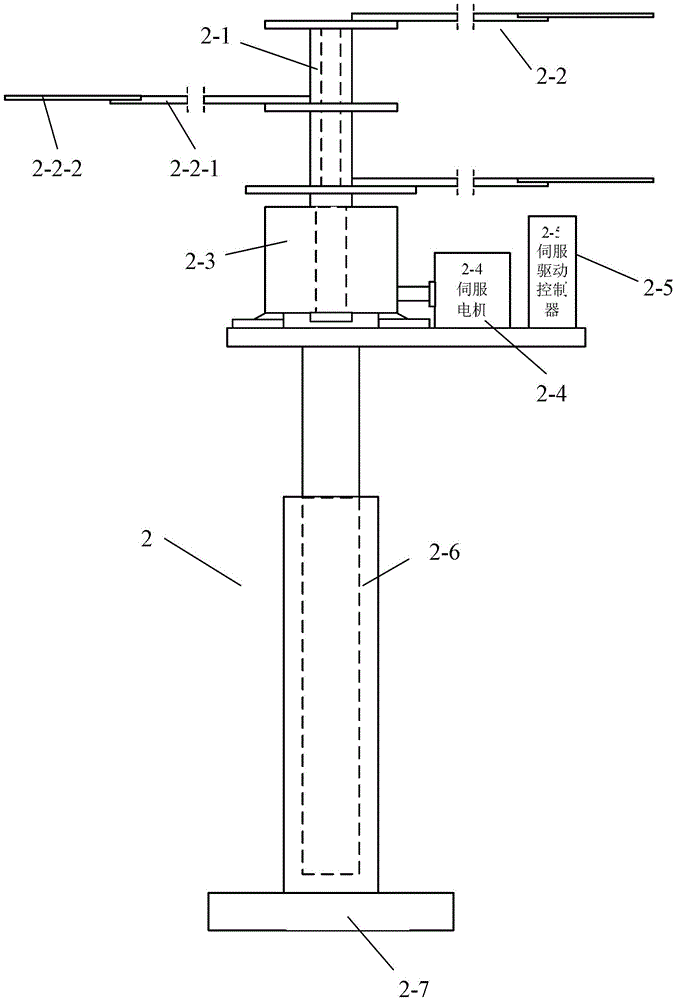
[0015] Specific implementation mode one: as Figure 1~6 As shown, the helicopter rotor blade dynamic balance parameter calibration device described in this embodiment includes two parts: the rotor blade measurement subsystem and the simulation blade calibration subsystem;
[0016] The rotor blade measurement subsystem 1 includes a helicopter rotor dynamic balance test bench 1-1, three lasers 1-2 and a signal conditioning circuit 1-3, a high-speed CPLD logic array device 1-4, and a high-speed DSP embedded data processor 1-5 and PC104 micro-control computer 1-6; the helicopter rotor dynamic balance test bench 1-1 is used to drive the three blades (reference blades) on the rotor to rotate, so that the three blades on the rotor are in the rotating state It can sequentially cut the laser optical path emitted by three lasers 1-2, and the rotor will generate 9 laser timing pulse signals every time it rotates. After the signal conditioning circuit 1-3 (photoelectric isolator) is used ...
specific Embodiment approach 2
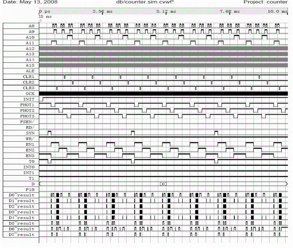
[0021] Specific implementation mode two: as Figure 1~6 As shown, the high-speed CPLD logic array device 1-4 described in this embodiment is designed with three 32-bit counters to measure the time interval of the sequential pulse signal, the time measurement accuracy is 0.05 μs, and the maximum counting time is 214.75s. The timing algorithm of rotor blade flapping parameters, according to Figure 9 , Figure 10 It can be concluded that:
[0022] h 1 =H*t 12 / (t 11 +t 12 )
[0023] h 2 =H*t 22 / (t 21 +t 22 )
[0024] h 3 =H*t 32 / (t 31 +t 32 )
[0025] h 1 -h 2 =H*[t 12 / (t 11 +t 12 )-t 22 / (t 21 +t 22 )]
[0026] h 1 -h 3 =H*[t 12 / (t 11 +t 12 )-t 32 / (t 31 +t 32 )]
[0027] where h 1 -h 2 and h 1 -h 3 are the height difference between the first blade and the second and third blades, respectively.
[0028] For the rotor blade shimmy angle parameter, the average time T taken by a certain blade to rotate through 120° 120 ,but:
[0029] T ...
specific Embodiment approach 3
[0036] Specific implementation mode three: as Figure 1~6 As shown, the simulated blade 2-2 in the simulated blade calibration subsystem 2 in this embodiment adopts a detachable structure. Other compositions and connections are the same as those in Embodiment 1 or 2.
PUM
 Abstract
Description
Claims
Application Information
 - R&D
- Intellectual Property
- Life Sciences
- Materials
- Tech Scout
- Unparalleled Data Quality
- Higher Quality Content
- 60% Fewer Hallucinations
Browse by: Latest US Patents, China's latest patents, Technical Efficacy Thesaurus, Application Domain, Technology Topic, Popular Technical Reports.
© 2025 PatSnap. All rights reserved.Legal|Privacy policy|Modern Slavery Act Transparency Statement|Sitemap|About US| Contact US: help@patsnap.com


