Planar vacuum glass welded by glass solders in microwave manner and subjected to edge sealing by strip frames, and manufacturing method of glass

A vacuum glass and welding surface technology, which is applied in glass forming, glass reshaping, glass manufacturing equipment, etc., can solve problems such as unsuitable for mechanization, automation and mass production, complex structure and process, and slow cooling speed

Inactive Publication Date: 2013-03-06
戴长虹
View PDF11 Cites 12 Cited by
  • Summary
  • Abstract
  • Description
  • Claims
  • Application Information

AI Technical Summary

Problems solved by technology

In the patent CN94192667.2 "Method for Manufacturing Vacuum Glass Windows", the edge sealing structure is designed so that the upper glass is slightly smaller than the lower glass in the two glasses, and the low melting point glass solder is placed on the edge steps formed by the two glasses, and the melted glass Solder flows into the gap between two pieces of glass due to capillary phenomenon. This method is the most representative and practical edge sealing technology at present, but it has the disadvantages of large amount of solder, uneven edges and high stress; patent CN95108228.0 "vacuum Flat glass and its manufacturing method" and CN96208977.X "vacuum flat glass", the edge of the glass plate is used to "chamfer" first, and the solder is placed in the chamfering groove. This method has the difficulty of distributing and the low-melting point glass solder is heated. Deficiencies that are easily lost during fusing and sealing; the patent CN02256440.3 "vacuum glass edge sealing structure" is to put auxiliary sealing strips on the upper periphery of the lower flat glass to prevent the loss of solder liquid. Although this method solves the problem of solder liquid's outward loss , but the process is complicated, and the auxiliary sealing strip takes up a large space, and it cannot solve the problem that the solder liquid flows into the glass; the edge sealing method of the vacuum glass proposed in the patent CN200620070302.7 "fully transparent vacuum glass" is to make the edge of the glass together with the glass The disadvantage is that the edge banding is not only expensive to manufacture but also cannot restrict the flow of low-temperature solder to the inside of the glass; patent CN200920314752.X "Edge banding structure of vacuum glass" is based on the glass and the The top glass and / or the base glass between the edge of the glass is made with a geometric filling groove, although it can improve the adhesion of the sealing filler between the base glass and the top glass, but the filling groove of the upper and lower glass is difficult. At the same time, the sealing packing is filled, and the random flow of the sealing packing cannot be restricted; Patent CN201010228110.5 "A Vacuum Glass Edge Sealing Method" is to put glass welding material around the periphery of the vacuum glass original plate, and set a layer inside the glass welding material The inner anti-seepage layer made of powdery or fibrous materials restricts the glass solder liquid from flowing into the vacuum glass. Compared with the existing technology, this method only restricts the glass solder liquid from flowing into the vacuum glass, and fails to overcome other shortcomings
In summary, the main disadvantages of the existing edge sealing methods are: first, the structure and process are complex, not suitable for mechanization, automation and mass production; Air port, not suitable for direct air extraction from the edge of the glass
[0004] The edge banding of the existing vacuum glass is generally to weld two pieces of glass together with low-temperature solder in a vacuum edge banding furnace. The disadvantages of conventional heating are long heating time, slow heating rate, slower cooling rate, and High energy consumption, poor heating uniformity, especially when making Low-E vacuum glass in a vacuum state, because there is no convective heat transfer, and the Low-E film seriously restricts radiation heat transfer, so its shortcomings are more prominent

Method used


Image

  • Planar vacuum glass welded by glass solders in microwave manner and subjected to edge sealing by strip frames, and manufacturing method of glass
  • Planar vacuum glass welded by glass solders in microwave manner and subjected to edge sealing by strip frames, and manufacturing method of glass
  • Planar vacuum glass welded by glass solders in microwave manner and subjected to edge sealing by strip frames, and manufacturing method of glass

Examples


Embodiment 1

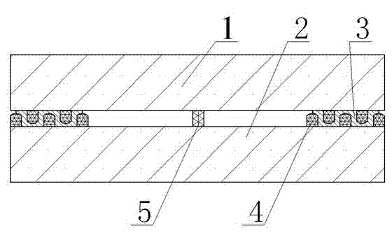
[0054] Embodiment 1: see figure 1 , the vacuum glass is composed of upper and lower glass, one of which is low-emissivity glass, and its production method is as follows: first, cut a piece of flat glass and a piece of low-emission glass of the required size according to the shape and size of the vacuum glass to be produced, and then perform edge grinding, After chamfering, film removal, cleaning and drying, use printing technology to print low-temperature glass powder paste on the upper glass to make an edge banding frame, and use polyester screen to print low-temperature glass powder paste on the lower glass to make an edge banding strip Frames and supports, where the upper glass has two edge banding frames, the lower glass has three edge banding frames, the size of the upper glass edge banding frame is between the lower glass edge banding frames, after the upper and lower glass are combined, The edge banding frame of the upper glass can be fitted between the edge banding fra...

Embodiment 2

[0057] Example 2: see figure 1 , the vacuum glass is composed of upper and lower glass, one of which is a low-emissivity glass, and its production method is as follows: first, cut a piece of flat glass and a piece of low-emission glass according to the shape and size of the vacuum glass to be produced, and perform edge grinding, chamfering, and removal film, after cleaning and drying, use a spray gun to spray low-temperature glass powder paste on the upper glass and the lower glass to make edge banding frames, in which the upper glass has two edge banding frames, the lower glass has three edge banding frames, and the upper glass has three edge banding frames. The size of the glass edge seal frame is between the lower glass edge seal frames. After the upper and lower glass are combined, the edge seal frame of the upper glass can be embedded between the edge seal frames of the lower glass. Each edge seal The width of the frame is 1.2mm and the height is 0.4mm; secondly, the two ...

Embodiment 3

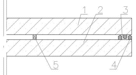
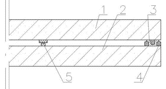
[0059] Embodiment 3: see figure 2 , one of the two pieces of vacuum glass is low-emissivity glass, and the other is tempered glass or half-tempered glass. Radiation glass, after grinding, chamfering, film removal, cleaning and drying, use printing technology to print low-temperature glass powder paste on the two pieces of glass to form an edge banding frame, in which the upper glass has an edge banding frame and the lower glass The glass has two edge banding frames. The size of the upper glass edge banding frame is between the two lower glass edge banding frames. After the upper and lower glass are combined, the upper glass edge banding frame can be embedded in the lower glass Between the two edge banding frames, the width of each edge banding frame is 1.8mm and the height is 0.25mm; secondly, the upper glass is sent into the high temperature furnace, and the edge banding is under the high temperature of 550~650℃ in the high temperature furnace The frame and the glass are si...


PUM

PropertyMeasurementUnit
melting pointaaaaaaaaaa
heightaaaaaaaaaa
widthaaaaaaaaaa

Abstract

The invention discloses vacuum glass. The vacuum glass is characterized in that the peripheries of the upper and lower glass are provided with edge sealing strip frames; and the upper and lower glass are welded together by low-temperature glass solders in a microwave oven, so that the vacuum glass is simpler and more convenient to manufacture, and a sealing effect is ensured by the embedding combination of the upper and lower edge sealing strip frames. A manufacturing method of the vacuum glass provided by the invention is simple in process, low in cost and high in production efficiency, can ensure reliable sealing connection and the good sealing effect, can be used for manufacturing vacuum glass without special extraction openings in mass by virtue of a one-step method, and can be used for manufacturing common vacuum glass and tempered vacuum glass.

Description

technical field [0001] The invention relates to the processing and manufacturing of vacuum glass, in particular to a method for making vacuum glass and its products. Background technique [0002] Vacuum glass is a new type of energy-saving and environmentally friendly product, which can be widely used in industrial and agricultural fields such as building doors and windows, glass curtain walls, solar products, agricultural greenhouses, refrigerators and refrigerators, and daily necessities for residents. Soundproofing and finishing materials. In the process of making vacuum glass, the structure and technology of edge sealing is the key technology to ensure that the periphery of vacuum glass is not deformed, does not produce excessive stress, does not leak air, and maintains the characteristics of tempered glass. In the patent CN94192667.2 "Method for Manufacturing Vacuum Glass Windows", the edge sealing structure is designed so that the upper glass is slightly smaller than ...

Claims


Application Information

Patent Timeline
Patent Type & Authority Applications(China)
IPC IPC(8): C03B23/24
CPCY02P40/57
Inventor 戴长虹
Owner 戴长虹
Why Eureka
Try Eureka