

Composite material deflating rate test system with self calibration function and method
A composite material and testing system technology, applied in the field of testing and self-calibration of vacuum gauges and mass spectrometers
Inactive Publication Date: 2013-03-13
北京宏宇永达科技发展有限公司
View PDF2 Cites 15 Cited by
- Summary
- Abstract
- Description
- Claims
- Application Information
AI Technical Summary
Problems solved by technology
[0003] Aiming at the demand for material outgassing rate testing in current research and production applications, the present invention establishes a composite material outgassing rate testing system with a wide range and self-calibration function. And the mass spectrometer has a self-calibration function, which improves the accuracy and reliability of the measurement data, and provides a composite material outgassing rate test system and method with a self-calibration function
Method used
View moreImage
Smart ImageViewing Examples

Examples
Embodiment
[0069] Note: The example is completed at a temperature of (23±3)°C.
Login to View More PUM
| Property | Measurement | Unit |
|---|---|---|
| Diameter | aaaaa | aaaaa |
| Surface area | aaaaa | aaaaa |
| Surface area | aaaaa | aaaaa |
Abstract
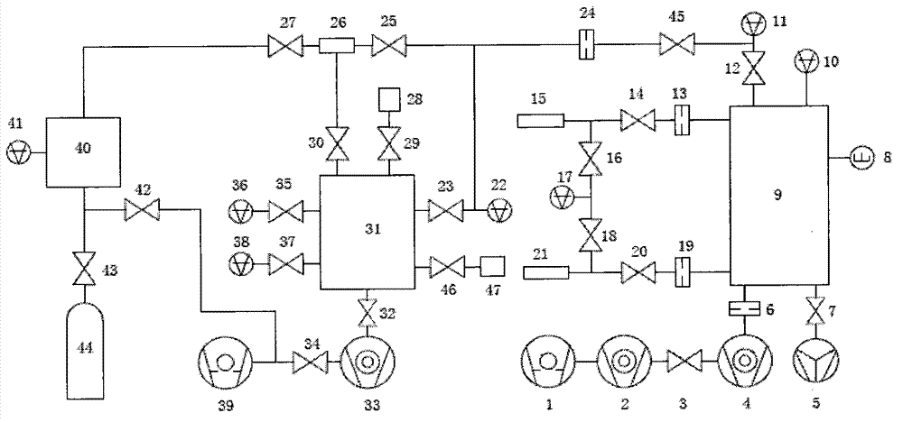
The invention belongs to the technical field of measurement, and in particular relates to a composite material deflating rate test system with self calibration function and a method. The system comprises a dry pump, a molecular pump, an ultra high vacuum metal angle valve, a getter pump, small pores, a quadrupole mass spectrometer, a vacuum chamber, an extractor gauge, a composite vacuum gauge, a sample room and a capacitance diaphragm gauge. The system combines three material deflating rate test methods, an accumulation method, a dynamic flow method and a double path method, and can test gas flow within the range of 1Pam<3> / s-6* 10<-12>Pam<3> / S ( if the surface area A equals to 6000 cm<2>, deflating rate measurement limit reaches 1*10<-15>Pam<3> / (s cm<2>)). The system covers material deflating rate test range 13 orders of magnitude, adopts a symmetric structure in design, and improves test efficiency and data reliability; besides, the system has function of automatic calibration on the ultra high vacuum gauge, the mass spectrometer and gas micrometeor, and has characteristics of multiple functions and high degree of integration.
Description
technical field [0001] The invention belongs to the technical field of measurement, and in particular relates to a testing system and method for the outgassing rate of materials under vacuum conditions, which are used for testing the outgassing rate of materials and for self-calibration of vacuum gauges and mass spectrometers. Background technique [0002] The outgassing rate of materials is one of the main characteristics of materials in a vacuum state. It is an important basis for the selection of vacuum instruments and equipment. It is of great significance for the selection of suitable materials for aerospace, semiconductor industry, high-energy physics and other application fields. The literature "Study on Measuring the Outgassing Rate of Materials by Small Hole Conductance Method", "Vacuum" Volume 47, Issue 3, 2010, Pages 55-58", introduced the method of measuring the outgassing rate of materials by the small hole conductance method, Its measuring range is 1×10 -7 ~1×...
Claims
Login to View More Application Information
Patent Timeline
 IPC IPC(8): G01N7/14
Inventor卢耀文
Owner北京宏宇永达科技发展有限公司