Centrifugal concentrator

A concentrator and centrifugal technology, applied in centrifuges, centrifuges with rotating drums, solid separation, etc., can solve the problems of screw and outer cone wear, design complexity, defects, etc., and achieve simplified design Effect

Inactive Publication Date: 2013-03-13
弗拉基米尔·米哈伊洛维奇·列皮奥欣 +1
View PDF6 Cites 6 Cited by
  • Summary
  • Abstract
  • Description
  • Claims
  • Application Information

AI Technical Summary

Problems solved by technology

[0010] The closest prior art is flawed due to design complexity and w...

Method used


Image

  • Centrifugal concentrator

Examples


Embodiment Construction

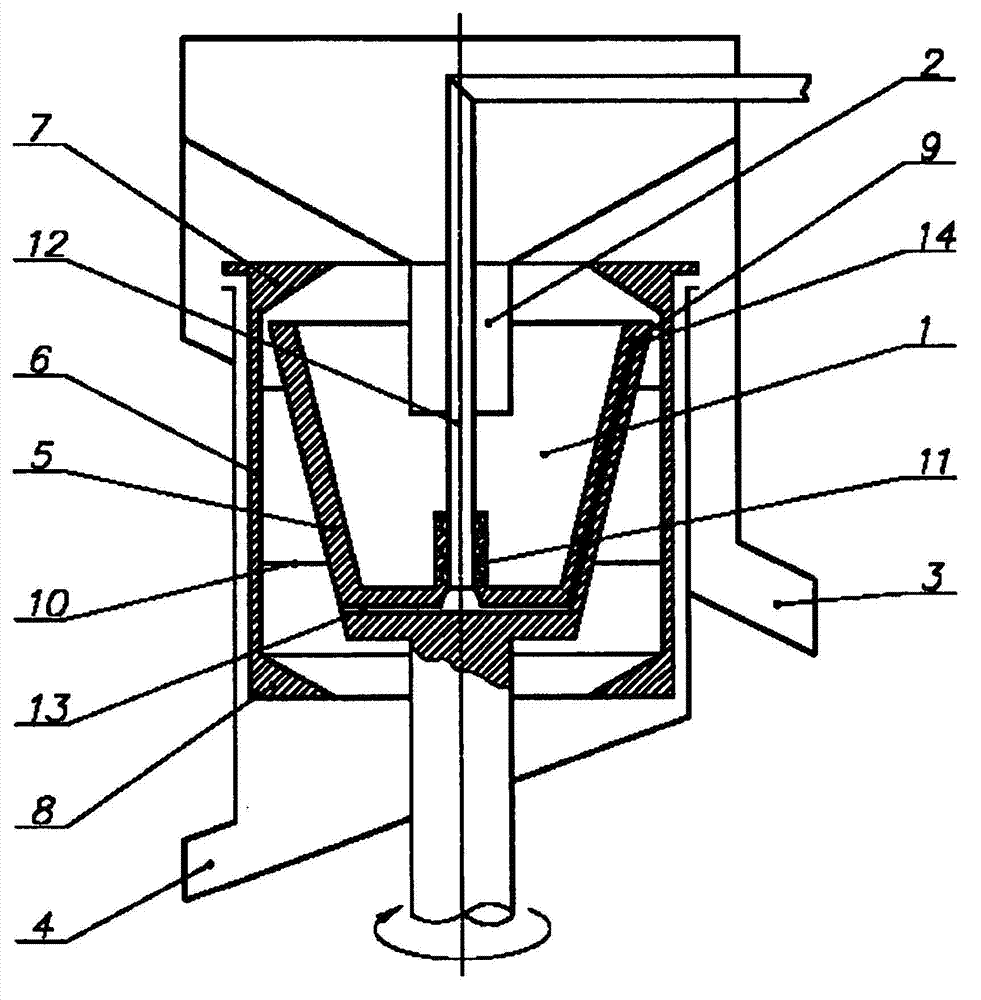
[0018] The concentrator operates as follows:

[0019] Raw material in the form of a slurry is pumped through the supply sleeve 2 into the rotor to the bottom of the cone 5 . Centrifugal force forces the slurry to be ejected against the walls of the cone and as it moves towards the boundary 7 the slurry is separated into layers. The heavy mineral deposits on the inner surface of the cone 5, slides towards the slot 9, and enters the casing 6 from which the slurry is flushed out of the casing at the boundary 8 by the flow exiting the tube 12 into the heavy debris collector 4 . Light debris flows over boundary 7 into receiver 3 . The inner diameter of border 8 may be equal to or smaller than the inner diameter of border 7 . The diameter length depends on the position of the rotor axis, the magnitude of the centrifugal force, and the mineral composition of the raw material. The outflow of heavy fragments of fixed inner diameter with boundary 8 is varied by the water flow fed th...


PUM


Abstract

The invention relates to the field of mineral processing and can be used for separating solid particles according to density, for example in factories in the polymetal industry, in tin production plants and in gold mining plants, both at the initial enrichment stage and in the processing of industrial waste. The technical result consists in simplifying the design and increasing the operational reliability of the apparatus as well as enhancing the quality of the concentrate produced. The concentrator comprises a rotor (1), mounted on a rotational shaft, a feed pipe (2), a light fraction receiver (3) and a heavy fraction collector (4). The rotor (1) comprises a cone (5) with a base, and a cylindrical shell (6) with an annular runoff lip (7) on the light fraction receiver side and an annular lip for collecting the heavy fraction (8). An annular gap (9) is provided between the edge of the large base of the cone and the cylindrical shell (6). The inner cone of the rotor is rigidly connected to the cylindrical shell. A sleeve (11) with a seal having a stationary tube (12) inserted therein is disposed along the rotor axis on the base of the inner cone. The sleeve (11) is connected to channels oriented inside the shell (6) for supplying flushing water to the outer shell.

Description

technical field [0001] The present invention relates to the concentration of minerals and can be used for separation of solids according to density, for example in complex metal industries, tin factories and gold mining industries for initial concentration and industrial waste heap disposal. Background technique [0002] It is well known that gravity separation is the most environmentally friendly method. Also, the centrifugal method is the most advanced and efficient technique for concentrating small particle mixtures (placer or crushed ore) containing small and fine fragments of heavy minerals. Centrifugal force helps to significantly reduce the size of recovered particles compared to traditional gravity flotation techniques. Where the noble and heavy components of the raw material can amount to a few thousandths or more, the concentrator has to continuously dispense the heavy pieces. [0003] Centrifugal continuous discharge thickeners are known in the art, for example ...

Claims


Application Information

Patent Timeline
IPC IPC(8): B03B5/32B04B1/00B04B7/08
CPCB04B1/00B04B7/08B03B5/32
Inventor 弗拉基米尔・米哈伊洛维奇・列皮奥欣
Owner 弗拉基米尔·米哈伊洛维奇·列皮奥欣
Why Eureka
Try Eureka