Hydrostatic actuator

A hydrostatic and actuator technology, applied in the direction of non-mechanical drive clutches, fluid pressure actuators, clutches, etc., can solve the problems of large ring piston diameter, high friction torque, expensive sealing device, etc., to reduce friction , reduce the volume, reduce the effect of the cross-sectional area of ​​the piston

Inactive Publication Date: 2013-03-13
SCHAEFFLER TECH AG & CO KG
View PDF9 Cites 7 Cited by
  • Summary
  • Abstract
  • Description
  • Claims
  • Application Information

AI Technical Summary

Problems solved by technology

Due to the large diameter of the annular piston, the sealing device for sealing the annular piston against the housing causes high frictional torques, high wear and loss of unloaded stroke
In addition, the seals used are expensive
The hydrostatic actuator has to be finally checked as a complete unit and requires complex rework in the event of a defect here

Method used


Image

  • Hydrostatic actuator
  • Hydrostatic actuator

Examples


Embodiment Construction

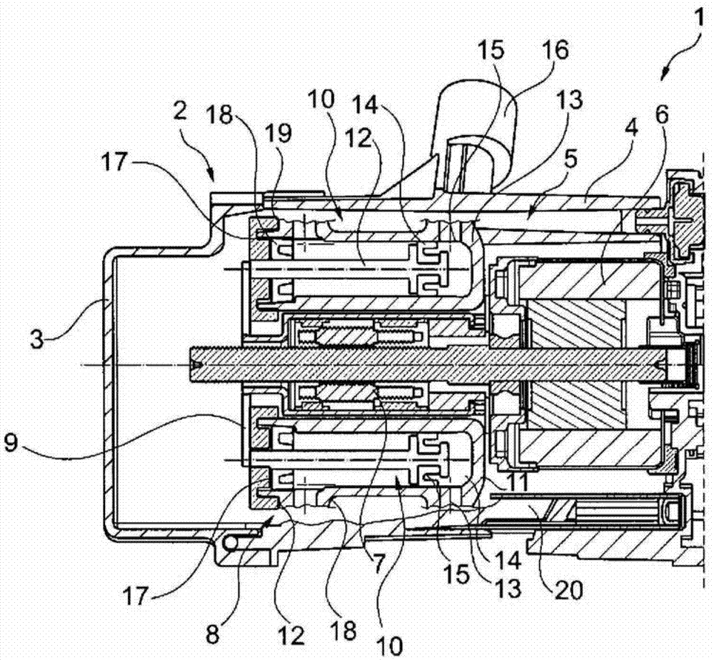
[0014] figure 1 A hydrostatic actuator 1 is shown in section, having a multi-part housing 2 with housing parts 3 , 4 . For the basic structure and function of the hydrostatic actuator 1 reference is made to the prior art mentioned above. The housing part 4 accommodates a drive unit 5 with an electric motor 6 and a planetary roller gear 7 driven by the motor rotor, as well as a master cylinder unit 8 . The housing part 3 serves as a closure cover for the housing part 4 .

[0015] The planetary roller gear 7 converts the rotational movement of the rotor into an axial movement and axially acts on the master cylinder unit 8 . For this purpose, a drive plate 9 is provided on the planetary roller gear 7 .

[0016] The master cylinder unit 8 is composed of master cylinders 10 , preferably evenly distributed over the circumference, which each have a master cylinder housing 11 and a piston 12 axially displaceable therein. The master cylinders are constructed as a separate structura...


PUM


Abstract

The invention relates to a hydrostatic actuator (1, 1a), in particular in a motor vehicle containing a drive unit (5), comprising an electric motor (6), a planetary roller gear system (7) that is driven by a rotor of the electric motor, and a hydrostatic master cylinder unit (8, 8a) which is driven by the planetary roller gear system and which is disposed around the planetary roller gear system. The aim of the invention is to increase the efficiency and reduce the production costs. This is achieved in that the master cylinder unit is formed from multiple master cylinders (10, 10a, 10b) which are distributed over the circumference with respect to a rotational axis of the rotor and each of which is connected to the planetary roller gear system.

Description

technical field [0001] The invention relates to a hydrostatic actuator, especially for use in motor vehicles, comprising a drive unit with an electric motor and a planetary roller transmission driven by the rotor of the electric motor and a surrounding planetary roller transmission driven by the planetary roller transmission Hydrostatic active cylinder unit with roller drive arrangement. Background technique [0002] Such hydrostatic actuators are disclosed in the non-prepublished German patent applications Nr. 102009051245.4, 102010009297.5 and 102010014673.0. In this case, the drive unit is provided with an electric motor whose rotor is connected to a planetary roller gear. Arranged around the planetary roller gear is a master cylinder unit with a master cylinder whose annular piston is displaced axially by the planetary gear. Due to the large diameter of the annular piston, the sealing device for sealing the annular piston relative to the housing causes high frictional ...

Claims


Application Information

Patent Timeline
Patent Type & Authority Applications(China)
IPC IPC(8): F16D29/00
CPCF16D29/005F15B7/08H02K5/10H02K7/06H02K7/108H02K11/38H02K17/32
Inventor T・拉姆霍费尔
Owner SCHAEFFLER TECH AG & CO KG
Why Eureka
Try Eureka