Initiative-driving spiral pipeline robot

一种螺旋管道、主动驱动的技术,应用在机器人领域,能够解决驱动轮转速降低、无法前进、结构能量损失大等问题,达到扩大适用范围、方便精确控制、调节精度高的效果

Active Publication Date: 2013-03-20
SOUTHWEST PETROLEUM UNIV
View PDF6 Cites 15 Cited by
  • Summary
  • Abstract
  • Description
  • Claims
  • Application Information

AI Technical Summary

Problems solved by technology

The existing screw moving device drives the drive frame with the drive wheel to rotate, and then the drive frame drives the drive wheel mounted on the edge of the drive frame to spiral along the inner wall of the pipeline to generate axial propulsion to make the robot go straight forward. The energy loss of this structure is large, and the transmission motion is unreliable
The speed of the robot is affected by the value of the included angle between the rotation axis of the driving wheel and the axis of the body. When the angle is small, the helical angle of the helical trajectory of the driving wheel is small, and the force driving the driving wheel to rotate is relatively large. The wheel speed is fast, and the robot runs smoothly, but because the helix angle of the helical trajectory is small, the forward speed is slow; with the increase of the angle, the force driving the driving wheel to rotate gradually becomes smaller, and the driving wheel speed decreases but the driving wheel moves faster. As the helix angle of the spiral trajectory increases, the forward speed of the robot will gradually increase with the increase of the angle, but when it exceeds a certain value, the rotation speed of the driving wheel will further decrease due to the force driving the driving wheel to rotate too small, resulting in the robot The forward speed decreases, while the stability of the robot operation decreases, and even the phenomenon that it cannot move forward
Therefore, the rotating speed of the driving wheel in the existing screw moving device will change with the change of the angle between the axis of rotation of the driving wheel and the axis of the body, and the running stability of the device is poor under different working conditions. At the same time, because the driving wheel is driven by The wheel frame drives the operation, therefore, it is difficult to realize the accurate positioning and small displacement adjustment of the robot, and the controllability is poor

Method used


Image

  • Initiative-driving spiral pipeline robot
  • Initiative-driving spiral pipeline robot
  • Initiative-driving spiral pipeline robot

Examples


Embodiment 1

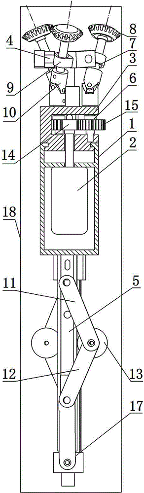
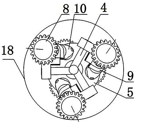
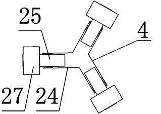
[0033] Such as figure 1 , figure 2 Shown, a kind of actively driven spiral pipe robot, it comprises driving wheel frame 3, body 1, guide wheel frame 5 and power unit 2, power unit 2 is fixed in body 1, and driving wheel frame 3 is rotatably installed on One end of the body 1, the guide wheel frame 5 is fixed on the other end of the body 1, and the driving wheel frame 3 is evenly distributed with three diameter reducing mechanisms 4 along the circumferential direction, that is, the angle between the adjacent variable diameter mechanisms 4 is 120 °, and the driving wheel frame 3 is also provided with a drive shaft 6 and a wheel shaft 7, and one end of the wheel shaft 7 is fixedly equipped with a drive wheel 8, the axis of rotation of the drive wheel 8 coincides with the axis of the wheel shaft 7, and each reducing mechanism 4 is provided with a bearing seat 9, Wheel shaft 7 is installed in the bearing housing 9 through bearings, drive shaft 6 is installed on the drive wheel fr...

Embodiment 2

[0038] Such as Figure 5 Shown, a kind of actively driven spiral pipe robot, it comprises driving wheel frame 3, body 1, guide wheel frame 5 and power unit 2, power unit 2 is fixed in body 1, and driving wheel frame 3 is rotatably installed on One end of the body 1, the guide wheel frame 5 is fixed on the other end of the body 1, the driving wheel frame 3 is provided with a variable diameter mechanism 4, the driving wheel frame 3 is also provided with a drive shaft 6 and a wheel shaft 7, and one end of the wheel shaft 7 The drive wheel 8 is fixedly installed, the axis of rotation of the drive wheel 8 coincides with the axis of the wheel shaft 7, the diameter reducing mechanism 4 is provided with a bearing seat 9, the wheel shaft 7 is installed in the bearing seat 9 through the bearing, and the drive shaft 6 is installed in the drive shaft through the bearing. On the wheel frame 3, the drive shaft 6 and the wheel shaft 7 are connected through a connector 10, the connector 10 is...

Embodiment 3

[0043] Such as Figure 9 Shown, a kind of actively driven spiral pipe robot, it comprises driving wheel frame 3, body 1, guide wheel frame 5 and power unit 2, power unit 2 is fixed in body 1, and driving wheel frame 3 is rotatably installed on One end of the body 1, the guide wheel frame 5 is fixed on the other end of the body 1, and the driving wheel frame 3 is evenly distributed with two diameter-reducing mechanisms 4 along the circumference, that is, the angle between the adjacent diameter-reducing mechanisms 4 is 180 °, and the driving wheel The frame 3 is also provided with a drive shaft 6 and a wheel shaft 7, and one end of the wheel shaft 7 is fixedly equipped with a drive wheel 8, the axis of rotation of the drive wheel 8 coincides with the axis of the wheel shaft 7, and each reducing mechanism 4 is provided with a bearing seat 9 , the wheel shaft 7 is installed in the bearing seat 9 through the bearing, and the driving shaft 6 is installed on the driving wheel frame 3...


PUM


Abstract

The invention discloses an initiative-driving spiral pipeline robot which comprises a machine body (1), a power unit (2), a driving shaft (6) and an axle (7); one end of the machine body (1) is provided with a driving wheel carrier (3); a reducing mechanism (4) is arranged on the driving wheel carrier (3); the axle (7) is arranged on the reducing mechanism (4); a driving wheel (8) is fixedly arranged on the axle (7); the driving shaft (6) and the axle (7) are connected through a connector (10); and the driving shaft (6) is connected with the output shaft of the power unit (2) through a transmission device. The initiative-driving spiral pipeline robot has the beneficial effects that the driving wheel is directly initiative-driving by the driving device, the scope of application of the robot is expanded, the operation is stable under the working conditions of different pipe diameters, and the axial force is large; and meanwhile, the axial position of the robot is adjusted by controlling the operation of the driving wheel, so that the adjustment precision is high, and the operation position of the robot is precisely controlled.

Description

technical field [0001] The invention relates to a robot walking in a pipeline, in particular to an actively driven spiral pipeline robot. Background technique [0002] At present, pipeline robot technology is a new type of technology that combines precision machinery, robotics, new materials, and control theory, which has emerged in recent years. Due to the use of many tiny pipes in modern industrial and agricultural production and daily life, such as steam generator heat transfer tubes in nuclear power plants, metallurgy, petroleum, chemical industry, urban plumbing supply, industrial pipes and gas pipes in the refrigeration industry, etc., these pipe systems The working environment is very harsh, prone to corrosion, fatigue damage, or the potential defects inside the pipeline develop into damage and cause leakage accidents. Therefore, the monitoring, diagnosis, cleaning and maintenance of pipelines have become the key to ensure the safe, smooth and efficient operation of ...

Claims


Application Information

Patent Timeline
Patent Type & Authority Applications(China)
IPC IPC(8): F16L55/32
CPCF16L55/32
Inventor 刘清友任涛陈永华
Owner SOUTHWEST PETROLEUM UNIV
Why Eureka
Try Eureka