Teaching demonstration device for electrostatic spinning

A demonstration device and electrospinning technology, applied in the field of electrospinning, can solve problems such as unsuitable teaching demonstration device, unsatisfactory teaching demonstration effect, insufficient spinning phenomenon, etc., achieve demonstration conditions, reliable method principle, and easy The effect of promotion

Inactive Publication Date: 2013-03-20
QINGDAO UNIV
View PDF10 Cites 2 Cited by
  • Summary
  • Abstract
  • Description
  • Claims
  • Application Information

AI Technical Summary

Problems solved by technology

Although there are many types of existing electrospinning devices, their composition and structure are relatively complicated, and most of them are not suitable for teaching demonstration devices
The Chinese patent application No. 201110255225.8 discloses "a rotating disk induction electrification type electrospinning device", which is designed and manufactured by induction electrification for experimental teaching, but because the device will induce The generator and electrospinning are separated to make its structure relatively complex; in addition, the device uses 30wt% polyvinylpyrrolidone (PVP, molecular weight 58,000) ethanol solution or office glue as the spinning precursor solution. Due to the thinner fibers formed by PVP, the spinning process is not easy to observe and a dense film structure will be formed on the collector after spinning, and the spinning phenomenon is not obvious enough; office glue is not easy to form spinning, and the amount of fibers is very small. The spinning phenomenon is not obvious, resulting in unsatisfactory teaching and demonstration effects

Method used


Image

  • Teaching demonstration device for electrostatic spinning
  • Teaching demonstration device for electrostatic spinning
  • Teaching demonstration device for electrostatic spinning

Examples


Embodiment

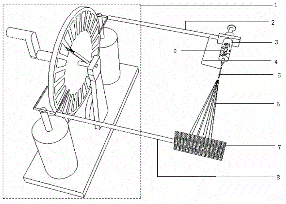
[0015] The main structure of this embodiment includes the electrostatic induction motor 1 with the discharge rod removed, the metal bracket 2 for the syringe, the syringe 3 filled with the spinning solution 9, the wire 4, the hollow stainless steel needle 5, the charged jet (or spinning fiber) 6, the metal The net collector 7 and the collector metal bracket 8; the electrostatic induction generator 1 with the discharge rod removed provides high-voltage static electricity for electrospinning, and one end of the metal bracket 2 of the syringe connects with a metal rod on the top of the Leiden bottle in the electrostatic induction generator 1 with the discharge rod removed Welded together, the other end is used to fix the syringe 3, the hollow stainless steel needle 5 is installed on the needle tube of the syringe 3, one end of the wire 4 is connected to the metal bracket 2 of the syringe, and the other end is connected to the hollow stainless steel needle 5, so that the storage can...


PUM

PropertyMeasurementUnit
lengthaaaaaaaaaa
lengthaaaaaaaaaa
lengthaaaaaaaaaa

Abstract

The invention belongs to the technical field of electrostatic spinning, and relates to a teaching demonstration device for the electrostatic spinning. The teaching demonstration device mainly comprises an electrostatic induction machine with a discharge rod being removed, an injector metal bracket, an injector filled with a spinning solution, a wire, a hollow stainless steel needle, electrified jet flows or spinning fibers, a metal net collector and a collector metal bracket, wherein one end of the injector metal bracket is welded with a metal bar at the top of a leyden jar in the electrostatic induction machine with the discharge rod being removed; the other end of the injector metal bracket is used for fixing the injector; one end of the wire is connected with the injector metal bracket; the other end of the wire is connected with the hollow stainless steel needle mounted on an injector needle tube; one end of the collector metal bracket is welded with a metal bar at the top of another leyden jar in the electrostatic induction machine with the discharge rod being removed; and the other end of the collector metal bracket is welded with the metal net collector. The teaching demonstration device is simple in structure, reliable in method and principle, low in fabrication cost, good in demonstration effect, high in safety and environmentally friendly; and demonstration conditions are easy to achieve.

Description

Technical field: [0001] The invention belongs to the technical field of electrospinning, and relates to an electrospinning teaching demonstration device, which is used for the teaching of nanotechnology or nanomaterials, and realizes economical, safe and intuitive teaching demonstration of electrospinning in nanotechnology. Background technique: [0002] The nanotechnology that emerged in the 1980s is a new branch of physics, chemistry, materials science, electronics, biology and other disciplines. Nanomaterials mainly include zero-dimensional atomic clusters, quantum dots, nanoparticles, one-dimensional Nanowires, nanotubes, nanofibers, two-dimensional nanofilms, three-dimensional nanosolid materials, and various nanocomposites. At present, major universities in China have successively offered undergraduate and master courses in nanotechnology or nanomaterials. However, there are still few related classroom demonstration experiments and students' innovative experiments. Th...

Claims


Application Information

Patent Timeline
Patent Type & Authority Applications(China)
IPC IPC(8): G09B25/02D01D5/00
Inventor 刘术亮龙云泽黄渊源孙彬张红娣
Owner QINGDAO UNIV
Why Eureka
Try Eureka