Electromagnetic valve driving device capable of bearing high frequency switching loss

A technology of solenoid valve drive and high-frequency switching, which is applied to valve devices, valve operation/release devices, valve details, etc., can solve the problems of occupying system software resources and complex implementation structures, and achieve improved drive capability, simple structure, Achieve instant protection and peak limiting effects

Active Publication Date: 2015-04-22
CHINA FIRST AUTOMOBILE
View PDF5 Cites 0 Cited by
  • Summary
  • Abstract
  • Description
  • Claims
  • Application Information

AI Technical Summary

Problems solved by technology

The trigger needs a high-frequency clock, the implementation structure is relatively complicated, and it also needs to occupy the software resources of the system

Method used


Image

  • Electromagnetic valve driving device capable of bearing high frequency switching loss
  • Electromagnetic valve driving device capable of bearing high frequency switching loss
  • Electromagnetic valve driving device capable of bearing high frequency switching loss

Examples


Embodiment Construction

[0020] The present invention will be further described below in conjunction with specific drawings and embodiments.

[0021] Such as figure 1 Shown:

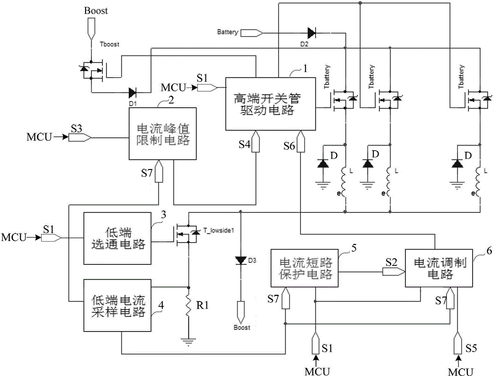
[0022] A solenoid valve drive device capable of withstanding high-frequency switching losses, including an MCU, and also includes a high-end switch tube drive circuit 1, a current peak limit circuit 2, a low-end gating circuit 3, a low-end current sampling circuit 4, and a current short-circuit protection circuit 5. Current modulation circuit 6, high voltage switch tube Tboost, multiple high-side drive branches, gate switch tube T_lowside1, first diode D1, second diode D2, third diode D3, sampling resistor R1; Each high-side drive branch includes a modulating switch tube Tbattery, a freewheeling diode D, and an injector solenoid valve L connected in series with the modulating switch tube Tbattery.

[0023] The high-voltage source Boost is connected to the drain of the high-voltage switching tube Tboost, the source of the high-...


PUM


Abstract

The invention provides an electromagnetic valve driving device capable of bearing high frequency switching loss. The electromagnetic valve driving device comprises an MCU (Microprogrammed Control Unit), and further comprises a high-end switch tube driving circuit, a current peak value limiting circuit, a low-end gate circuit, a low-end current sampling circuit, a current short-circuit protective circuit, a current modulator circuit, a high voltage switch tube, a plurality of high-end driving braches, a gating switch tube, a first diode, a second diode, a third diode and a sampling resistor. Each high-end driving branch comprises a modulation switch tube, a fly-wheel diode and an electromagnetic valve of an oil atomizer connected with the modulation switch tube in series. The current short-circuit protective circuit comprises a first not gate, a first or gate, a first comparator, a nineteenth resistor, a twentieth resistor, a tenth resistor and a tenth capacitor. The current peak value limiting circuit comprises a second not gate, a second or gate, a second comparator, an output or gate, a twenty-first resistor, a twenty-second resistor, a twentieth resistor and the twentieth capacitor. The electromagnetic valve driving device capable of bearing high frequency switching loss provided by the invention is used to drive the electromagnetic valve of the oil atomizer.

Description

technical field [0001] The invention relates to an electromagnetic valve driving device, in particular to an electromagnetic valve driving device capable of withstanding high-frequency switching loss. Background technique [0002] The current patent CN202194730U and the known solenoid valve drive topology in CN1651742A all adopt the form of several low-end gates sharing a high-end switch. This structure can meet the driving requirements of general engine working conditions, and can also meet the driving requirements of electromagnetic valves with large inductive parameters. However, for extreme working conditions that require high-speed combined multiple injections, or require the use of new injectors with small inductive parameters of high-frequency modulation current, the high-end modulation switch tube of the driving upper bridge of this topology structure is prone to heat damage. . The new injectors now have the characteristics of fast response time and high injection ...

Claims


Application Information

Patent Timeline
Patent Type & Authority Patents(China)
IPC IPC(8): F02D41/30F16K31/06
Inventor 谢宏斌曾伟蒋诚张爱云俞谢斌高威徐剑飞
Owner CHINA FIRST AUTOMOBILE
Why Eureka
Try Eureka