High-resolution large-range optical fiber strain sensor and probe thereof

A sensor probe, optical fiber strain technology, used in instruments, measuring devices, optical devices, etc., can solve the problems of slow measurement speed, difficult to obtain high precision, limited measurement range, etc., to avoid the scanning process, achieve high-speed measurement, The effect of high strain measurement accuracy

Inactive Publication Date: 2013-03-27
无锡联河光子技术有限公司
View PDF5 Cites 9 Cited by
  • Summary
  • Abstract
  • Description
  • Claims
  • Application Information

AI Technical Summary

Problems solved by technology

Another large-range static strain sensor uses a tunable laser to scan a pair of fiber gratings to obtain a static strain of more than 100micro-strain (Q.Liu, et al., "Ultra-high-resolution large-dynamic-range optical fiber static strain sensor using Pound-Drever-Hall technique,"Opt.Lett.,vol.36,pp.4044-4046,2011). However, its measurement accuracy is affected by the nonlinearity in laser wavelength tuning, and it is difficult to obtain high precision
Another high-precision strain sensor adopts a sideband detection technique and uses a wavelength-tunable laser to detect a pair of identical fiber optic probes to obtain high strain accuracy (Q.Liu, et al., "Sub-nano resolution fiber optic static strain sensor using a sideband interrogation technique,"Opt.Lett.,37(3):434-436(2012)), but its measurement range is limited by the frequency range of the sideband modulation signal, and the measurement speed is relatively slow
At the same time, there is no good method for optical fiber strain sensing technology that can achieve ultra-high strain accuracy and ultra-large strain measurement range.

Method used


Image

  • High-resolution large-range optical fiber strain sensor and probe thereof
  • High-resolution large-range optical fiber strain sensor and probe thereof
  • High-resolution large-range optical fiber strain sensor and probe thereof

Examples


Embodiment Construction

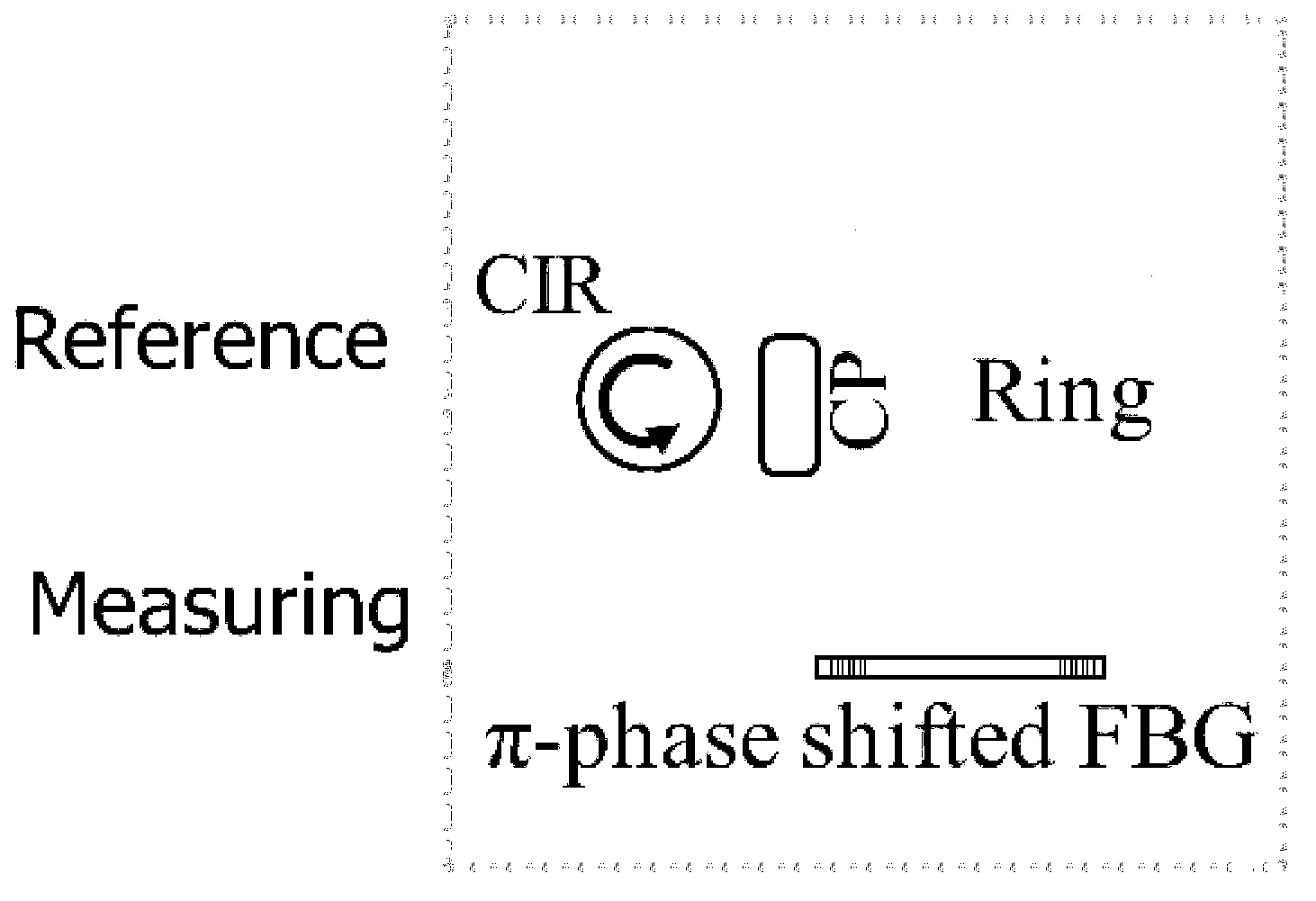
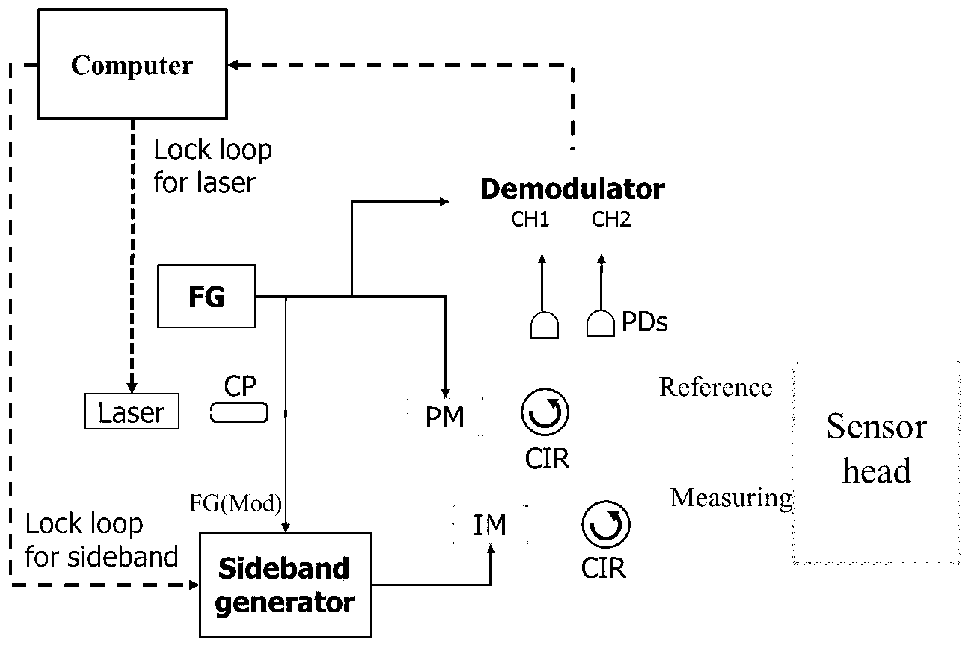
[0020] Such as figure 1 A high-resolution and large-range fiber optic strain sensor probe is shown, which has a fiber ring as a reference and a fiber Bragg grating (FBG) for measuring strain, including ordinary gratings and phase shifted gratings π-phase shifted FBG , the phase-shifted grating has better performance). Fiber Bragg Grating FBG is a strain measurement component, and the deformation to be measured is applied to the FBG; the fiber ring is a reference component, which is not affected by external strain. Fiber ring and FBG are located close to each other to achieve the same temperature. FBG has a resonant frequency (for ordinary FBG, the resonant frequency refers to the optical frequency with high reflectivity; for π-phase shifted FBG, it refers to a very narrow high transmittance in the high reflectivity frequency range optical frequency), which is a linear function of the strain to be measured and temperature, while the fiber ring has some series of discrete res...


PUM


Abstract

The invention discloses a probe of a high-resolution large-range optical fiber strain sensor. The probe comprises an optical fiber annular cavity as a reference and an optical fiber grating for measuring strain. The optical fiber annular cavity is mutually close to that of the optical fiber grating. In terms of the high-resolution large-range optical fiber strain sensor, after laser produced by a laser device passes through a beam splitter, a beam of light is used for detecting the optical fiber annular cavity of the sensor after passing through a phase modulator, and an optical sideband signal generated by another beam of light passing through an intensity modulator is used for detecting the optical fiber grating of the sensor. Reflecting light of a detection signal is converted into an intensity signal through a light intensity signal and is demodulated by a demodulator to be used for controlling central frequency of the laser device and that of a sideband signal generator. A strain measuring range exceeding 100micro-strain can be achieved in low sideband modulation frequency of the sensor, and ultrahigh strain measuring precision is kept. Laser wavelength scanning process is avoided, and high-speed measurement can be achieved.

Description

technical field [0001] The invention relates to a high-resolution and large-range optical fiber strain sensor, which uses an optical fiber device as a probe to accurately measure the deformation of the earth's crust and the like. Background technique [0002] The study and prediction of natural disasters such as volcanoes and earthquakes are important social issues in densely populated areas. In this field, in order to grasp the movement and stress state of the crust, it is necessary to monitor the deformation of the crust over a long period of time at as many locations as possible. The period of crustal deformation covers a quasi-static range from tens of milliseconds to infinite time, and its fluctuation ranges from a few nano-strains to hundreds of micro-strains. In order to accurately obtain the deformation information of the earth's crust, the sensors used need to have the ability to measure static strain, ultra-high strain measurement accuracy and large measurement ra...

Claims


Application Information

Patent Timeline
Patent Type & Authority Applications(China)
IPC IPC(8): G01B11/16
Inventor 刘庆文何祖源
Owner 无锡联河光子技术有限公司
Why Eureka
Try Eureka