Energy pack

An energy and negative electrode technology, applied in the field of energy packs, can solve the problems of energy loss, complex structure of energy storage devices, affecting energy utilization efficiency, etc., to achieve the effect of expanding the scope of application and simple structure

Active Publication Date: 2013-03-27
BEIJING INST OF NANOENERGY & NANOSYST
View PDF5 Cites 14 Cited by
  • Summary
  • Abstract
  • Description
  • Claims
  • Application Information

AI Technical Summary

Problems solved by technology

These energy storage systems can only be used for energy storage and cannot generate electricity by themselves
[0004] In the existing technology, to convert the energy of nature into electric energy to charge the energy storage device, it can only be integrated through the connection of external circuits, and often through units such as rectification, which not only makes the structure of the energy storage device complicated, but also the current After the transmission in the external circuit and these external units, a certain amount of energy loss will be generated, which will affect the energy utilization efficiency

Method used


Image

  • Energy pack
  • Energy pack
  • Energy pack

Examples


Embodiment 1

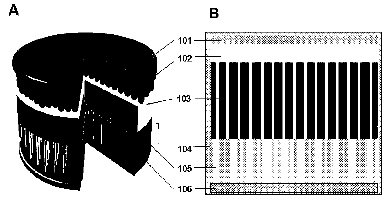
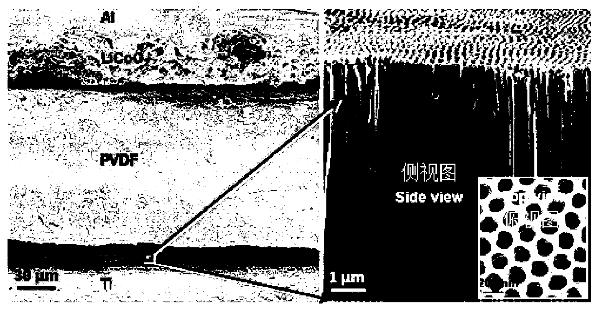
[0037] The energy package in this embodiment is based on the fact that the positive electrode material is LiCoO 2 particles, the anode material is TiO 2 Nanotube arrays (or silicon nanowire arrays) for Li-ion battery construction. For a schematic structural diagram of the energy pack of this embodiment, see figure 2 , wherein, Figure A is a schematic diagram of the overall structure of the energy pack, Figure B is a cross-sectional view of the energy pack, and the positive pole of the energy pack is covered with LiCoO 2 The metal foil 101 of the particles 102, the negative electrode is prepared with a metal foil 106 with nanostructures 105 on the surface opposite to the positive electrode, and the LiCoO on the surface of the positive electrode 2 The particles 102 and the nanostructures 105 on the surface of the negative electrode are arranged face to face. The positive and negative electrodes are separated by an electrolyte solution 104, and a piezoelectric ion transport l...

Embodiment 2

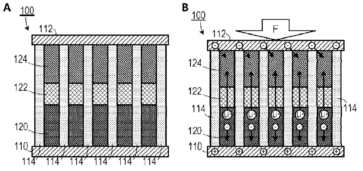
[0049] The energy pack of this implementation example is still an electrochemical storage device based on a lithium-ion battery, and the specific structure is as follows: Figure 6 As shown, among them, Figure A is a schematic diagram of the overall structure of the energy pack, and Figure B is a cross-sectional view of the energy pack. The positive electrode of the energy pack 200 is prepared with LiCoO on the surface 2 The metal foil 212 of particles 216, the negative electrode is prepared with the metal foil 210 with nanostructure 214 on the surface opposite to the positive electrode, and the LiCoO on the surface of the positive electrode 2 The particles 216 and the nanostructures 214 on the surface of the negative electrode are arranged face to face. The positive and negative electrodes are separated by an electrolyte, and include a piezoelectric ion transport layer 218 between the positive and negative electrodes, and the piezoelectric ion transport layer also includes n...

Embodiment 3

[0056] The energy pack of this embodiment can also be realized by a supercapacitor system. Supercapacitor systems generally have a similar structure to lithium-ion batteries: both have two electrode sheets and a separator placed in between. The difference is that the energy storage of supercapacitors is mainly achieved by the physical adsorption of carriers and counter ions at the electrode / electrolyte interface leading to an electric double layer. In a supercapacitor, the two electrodes are usually the same substance, and the electrolyte can be either an aqueous or an organic solution.

[0057] The energy pack in this embodiment uses a piezoelectric ion transport layer instead of the diaphragm of a supercapacitor. For a schematic diagram of its structure, see Figure 7 , wherein, Figure A is a schematic diagram of the overall structure of the energy pack, and Figure B is a cross-sectional view of the energy pack. The anode of the energy pack 400 is a metal material 401 prep...


PUM


Abstract

The invention provides an energy pack. The energy pack comprises a positive electrode and a negative electrode separated by electrolyte, and also comprises a piezoelectric ion transmission layer positioned between the positive electrode and the negative electrode, wherein the piezoelectric ion transmission layer generates a piezoelectric field pointing from the positive electrode to the negative electrode under the action of mechanical force. According to the energy pack, a piezoelectric ion transmission layer material is introduced between the positive electrode and the negative electrode to replace inherent units of device construction of a cell or a super-capacitor. Therefore, the energy storage characteristics of the existing electrochemical system is nondestructively kept, and ions in the electrolyte are driven to migrate by piezoelectric potential generated by the piezoelectric material under the mechanical action, thereby causing nonuniform redistribution of ion concentration to trigger the charging process. Accordingly, the energy pack provided by the invention has a function of self energy charging.

Description

technical field [0001] The invention relates to the technical field of energy storage, in particular to an energy pack capable of storing mechanical energy as electrical energy. Background technique [0002] Energy conversion and storage are the most important technologies for green and renewable energy science today. They are usually implemented based on discrete units designed according to different approaches. [0003] For energy conversion and utilization, according to the nature of energy in nature (such as solar energy, thermal energy, chemical energy and mechanical energy, etc.), people have developed various mechanisms to convert these energies into electrical energy. For example, for small-scale mechanical energy, piezoelectric nanogenerators are an effective way to convert low-frequency biomechanical energy into electrical energy. For traditional energy storage, take electrochemical energy storage systems (such as capacitors, batteries, etc.) as an example, they ...

Claims


Application Information

Patent Timeline
Patent Type & Authority Applications(China)
IPC IPC(8): H01M10/058H01M2/16H01G11/00
CPCY02E60/12Y02E60/10Y02P70/50
Inventor 王中林王思泓薛欣宇
Owner BEIJING INST OF NANOENERGY & NANOSYST
Why Eureka
Try Eureka