
Magnetized salient pole type mixed excitation synchronous motor

A hybrid excitation synchronous and salient pole technology, applied in the direction of synchronous machine, magnetic circuit shape/style/structure, electrical components, etc., can solve the problem that the rotor structure is difficult to unify the hybrid excitation motor, affect the sine of the magnetic field waveform, and the harmonic component of the magnetic field Increase and other problems, to avoid demagnetization effect, good symmetry, enhance the effect of security

Active Publication Date: 2013-03-27
SHANGHAI EDRIVE +2
View PDF5 Cites 61 Cited by
  • Summary
  • Abstract
  • Description
  • Claims
  • Application Information

AI Technical Summary

Problems solved by technology

In the case of applying the quadrature axis current and the direct axis current of the field weakening effect, the IPM rotor can produce a positive weak magnetic reluctance torque, while the electrically excited rotor produces a reverse reluctance torque, so the two rotor structures Difficult to unify in hybrid excitation motors
[0004] In addition, the weak magnetic reluctance torque generated by the general IPM motor will have certain side effects: 1) The rotor of the general IPM motor has a large quadrature axis inductance, so the armature reaction of the quadrature axis is quite violent, which will seriously affect the magnetic field waveform 2) In order to generate positive torque, there will be a certain magnitude of weak magnetic direct axis current, which will increase the harmonic component of the magnetic field while weakening the fundamental magnetic potential; 3) Weak magnetic direct The axial current will have a strong demagnetization effect on the magnetic steel, which poses a threat to the safety of the magnetic steel

Method used


Image

  • Magnetized salient pole type mixed excitation synchronous motor
  • Magnetized salient pole type mixed excitation synchronous motor
  • Magnetized salient pole type mixed excitation synchronous motor

Examples


Embodiment Construction

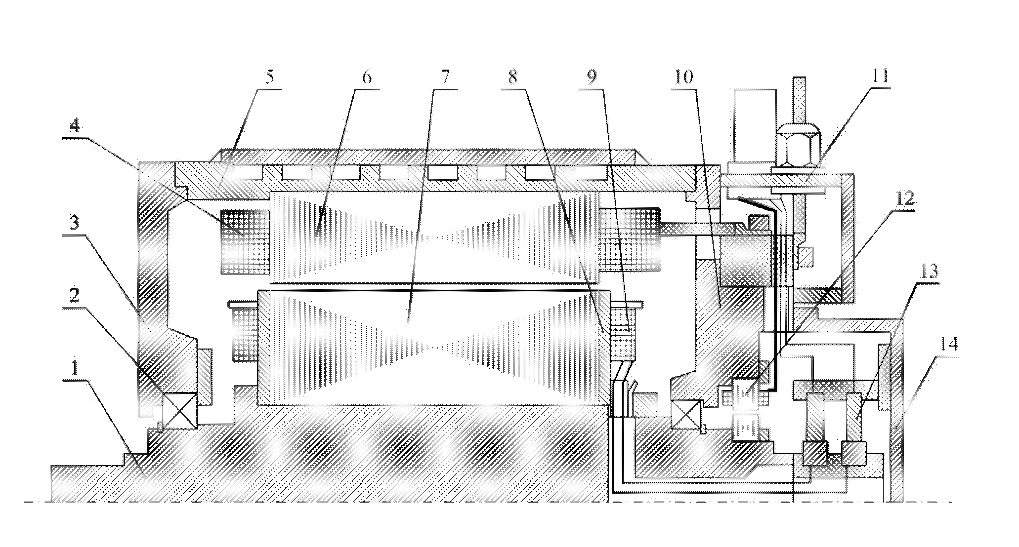
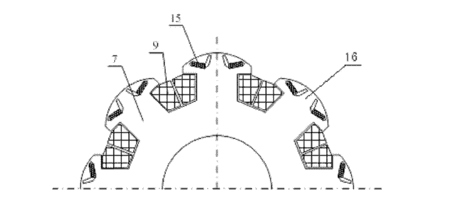
[0028] see figure 1 , figure 2 , the present invention magnetization type salient pole hybrid excitation synchronous motor, including shaft 1, bearing 2, front end cover 3, stator winding 4, casing 5, stator core 6, rotor core 7, permanent magnet steel 15, rotor pressure plate 8 , Electric excitation winding 9, rear end cap 10, junction box assembly 11, resolver 12, brush 13 and brush junction box 14.

[0029] In the present invention, the stator core 6 and the stator winding 4 adopt a conventional permanent magnet synchronous motor stator structure; the rotor core 7 is similar to the rotor of a salient-pole electric excitation synchronous motor, has an electric excitation winding, and the air gap of the quadrature axis is greater than that of the direct axis .

[0030] Each rotor magnetic pole of the rotor core 7 in the present invention is respectively designed with two "V"-shaped magnetic steel grooves, and magnetic steel 15 of the same polarity is respectively placed i...


PUM


Abstract

A magnetized salient pole type mixed excitation synchronous motor mainly comprises a stator and a rotor, wherein the stator is of structure identical with that of a stator of a conventional permanent-magnet synchronous motor, the rotor is similar to a rotor of a salient pole type excitation synchronous rotor in shape and provided with an electromagnetic winding, and quadrature axis air gap is larger than direct axis air gap. Each magnet pole of the rotor is respectively provided with two 'V'-shaped magnetic steel grooves, steel magnets with same polarity are respectively disposed in the magnetic steel grooves, and finally, the double 'V'-shaped mixed excitation magnetic pole structure with quadrature axis magnetic resistance higher than direct axis magnetic resistance. By means of the excitation magnetic winding, induced potential can be directly adjusted, and irreversible demagnetization on the steel magnets can be avoided. Further, on the condition of applying quadrature axis current and magnetizing direct axis current at the same time, magnetized magnetic resistance torque component can be generated so as to increase torque density of the motor.

Description

technical field [0001] The invention relates to a motor, in particular to a hybrid excitation synchronous motor which can control an air gap magnetic field through an electric excitation winding on a rotor and has a magnetization-increasing reluctance torque. Background technique [0002] The hybrid excitation motor combines the characteristics of the permanent magnet motor and the electric excitation motor, which can simply, flexibly and economically adjust the air gap magnetic field of the motor and change the characteristics of the induced potential of the winding. However, the general hybrid excitation motor is difficult to compare with the traditional permanent magnet motor in terms of power density, and due to the more complex structure, the processing is more difficult and the practical value is small. Therefore, there is basically no hybrid excitation motor that has been mass-produced. . [0003] The general IPM motor rotor structure has a direct axis inductance sma...

Claims


Application Information

Patent Timeline
IPC IPC(8): H02K21/00H02K1/27H02K1/24
Inventor 应红亮
Owner SHANGHAI EDRIVE
Learn More