
Engine body for hot air engine

A technology of hot air engine and fuselage, which is applied in the direction of hot air variable displacement engine devices, machines/engines, mechanical equipment, etc., and can solve problems such as uneven temperature of working medium, uneven cooling effect, and complicated layout of cooling water pipelines

Active Publication Date: 2013-04-03
SHANGHAI MICROPOWERS
View PDF4 Cites 3 Cited by
  • Summary
  • Abstract
  • Description
  • Claims
  • Application Information

AI Technical Summary

Problems solved by technology

[0007] The technical problem to be solved by the present invention is to provide a fuselage for a heat engine, which solves the problem that the traditional fuselage cooling water pipeline layout is complicated, the cooling effect is uneven, and the temperature of the working fluid in the cylinders of the four cylinders of the heat engine is uneven. question

Method used


Image

  • Engine body for hot air engine

Examples


Embodiment Construction

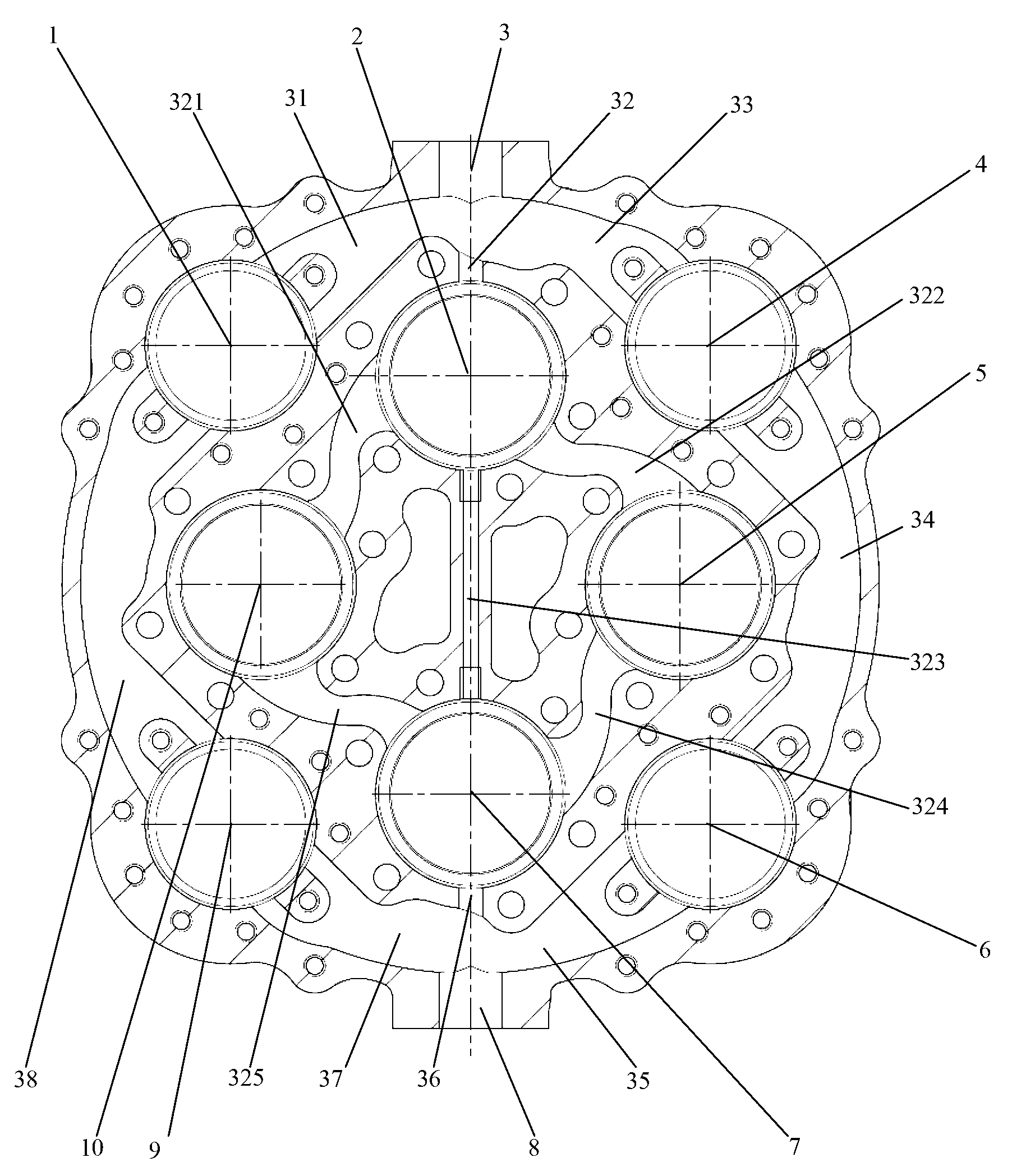
[0019] figure 1 Shown is an embodiment of the present invention. The fuselage is integrated. In order to improve production efficiency and reduce costs, the fuselage is integrally cast from cast aluminum and then machined. The fuselage is provided with a cylinder liner installation hole for installing the cylinder liner of the heat engine and a cooler installation hole for installing the cooler, and the body is suitable for the heat engine in which the cylinder liner and the cooler are arranged separately. The cylinder liner installation holes on the fuselage are arranged in a square shape, and a cooler installation hole is arranged near each cylinder liner installation hole.

[0020] A cooling water flow channel and a working medium flow channel are also arranged on the fuselage. For the convenience of peripheral piping layout, the fuselage is only provided with a cooling water inlet 3 and a cooling water outlet 8 . In order to improve the cooling effect, the cooling water c...


PUM


Abstract

The invention discloses an engine body for a hot air engine. Four cylinder sleeve installing holes and cooler installing holes as well as a cooling water inlet, a cooling water outlet and a cooler flow passage are arranged in the integral engine body, the cylinder sleeve installing holes and the cooler installing holes are in square arrangement in a separated way, the cooler installing holes are arranged near the adjacent cylinder sleeve installing holes, the number of the cooling water inlet and the number of the cooling water outlet are respectively one, cooling water flow passages are divided into an outer flow passage and an inner flow passage, cooling water of the outer flow passage is communicated with the cooler installing holes and is used for cooling a cooler, cooling water of the inner flow passage is communicated with the cylinder sleeve installing holes and is used for cooling a cylinder sleeve, and a cooling water supplementing flow passage is also arranged between the No.1 cylinder sleeve installing hole and the No.3 cylinder installing hole at the far end and is used for enhancing the cooling effect of the No.3 cylinder installing hole at the far end. The engine body has the characteristics of simple structure and good cooling effect and is suitable for being used by a Stirling engine.

Description

technical field [0001] The invention relates to a heat engine, in particular to a fuselage for the heat engine. Background technique [0002] The fuselage is one of the key parts of the heat engine, especially for the four-cylinder double-acting heat engine, the structure of the fuselage is extremely complicated, and there are installation holes for the cylinder liner of the heat engine, working medium flow channels, and cooling water flow channels inside. The body is also the installation base for the heater, pressure shell and other parts of the heat engine. The upper part is connected to the external combustion system, and the lower part is connected to the transmission system to form the whole heat engine. [0003] The Chinese patent No. ZL2010201614031 discloses a combined fuselage for a heat engine, which includes an upper fuselage and a lower fuselage, the upper fuselage and the lower fuselage are separate, and the two are connected into one body by bolts; A cooling ...

Claims


Application Information

Patent Timeline
IPC IPC(8): F02G1/053
Inventor 朱辰元顾根香梁鹏飞凌虹周建明刘靖飙梁伟青
Owner SHANGHAI MICROPOWERS
Learn More